
4 layers71.8 × 40.5 mm

eeg
Eeg is an open-source printed circuit board by gianisalive, from the gianisalive/lucid_candy repository on GitHub. It is a 2-layer board of 39.9 × 50.5 mm with 77 parts on 68 nets, routed with 683 tracks and 46 vias.
It is built around the ADM8660ARZ, ADP7182ACPZN-2.5R7 and ADS1299IPAG, with the TPD4E1B06DCKR-TP among its other parts. Its parts include 39 capacitors, 21 resistors, 6 diodes, 5 ICs and 2 connectors.


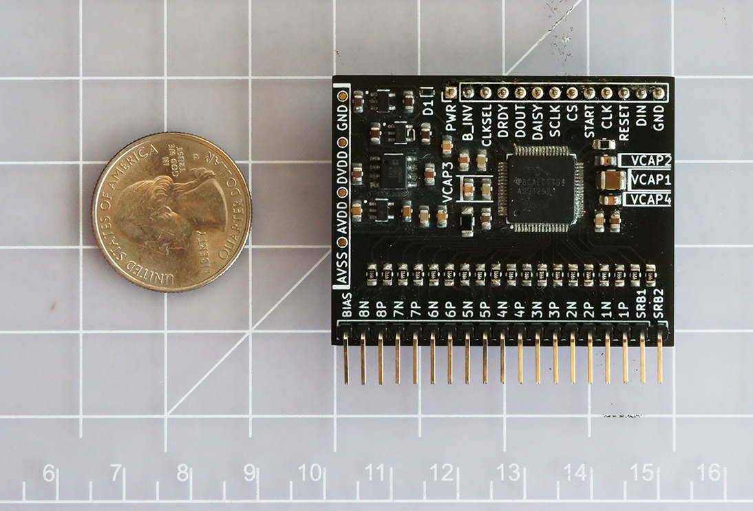 A bare minimum 8 channel EEG board with TI ads1299 chip. It can be driven with any microcontroller that has 3.3V logic. Multiple boards can be chained together to record with 16 or 24 channels. This repository includes KiCad files and SPI example.
It still needs a lot of improvement, professional guidance and review. In no way it's fully tested to perform under clinical setting. Please use basic principles to test and evaluate before using it. All suggestions are highly appreciated: gianisalive@gmail.com
No one really should, but if you're a newbie in electronics, software, and neuroscience, and want to learn more by building, then this might be a thing for you. If you're just looking for an affordable EEG, there're better open source ones out there, such as OpenBCI.
|-- lucid_candy
|---- component_datasheet------important datasheet of the components used for the board
|---- e_component---------------all the KiCad pcb footprint (from SnapEDA) for the components
|---- eeg------------------------KiCad design files
|---- firmware-------------------example of Arduino DUE communicating with the board via SPI
|---- gerber_zip-----------------same file used to produce the current board with JLCPCB
The philosophy with current version of the design is to work within TI's recommendation, and choose components with least amount of tolerance/inductance to develope a baseline. In the future, any design improvement can be evaluated/compared to the current design.
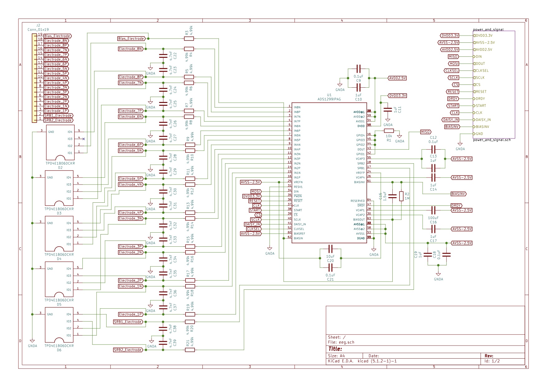
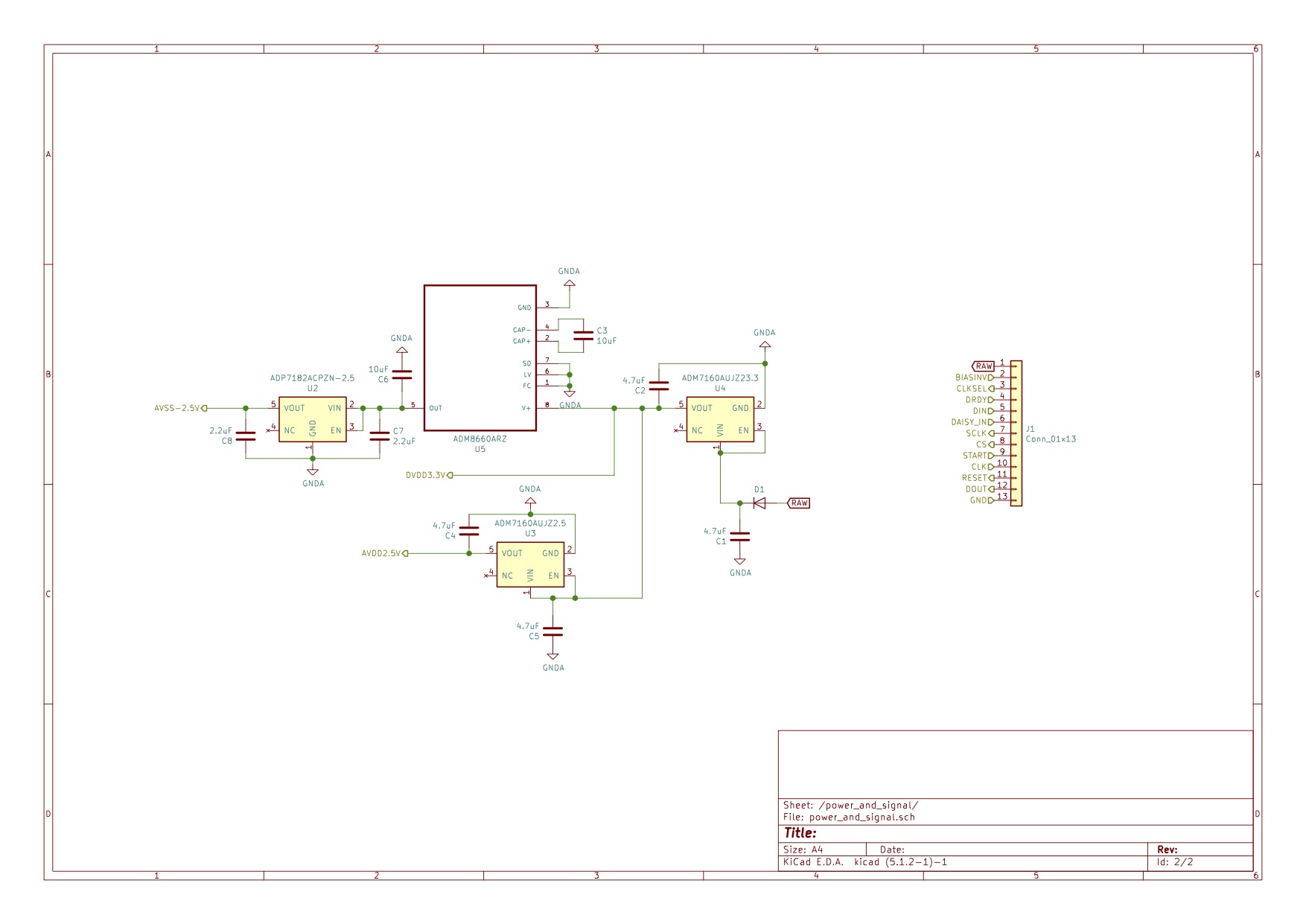
All the component used can be found here. Some of these are pretty over priced. In most situations, you can probably get away with cheaper parts.
Overview:
Power up sequence:
Data conversion:
Fully assembled device with current Arduino firmware is tested with a calibrated Keysight DSOX1204G oscilloscope/function generator.
In a nutshell, eliminating noises and extracting the signal is one of the most chanllenging part when it comes to designing the hardware and the software.
Neurons communcate via electrical signals (Action Potentials). When neurons are ready to send signals to neighboring neurons, they produce about 100 mV spike in less than 3 ms. These signals are further attenuated (reduction in signal strength) by the surrounding anatomical structures. When the electrode receives the signal, it's been attenuated to uV scale. In order to extract the signals, we need to filter out the noise with minimal distortion to the signal. There're few methods suggest that're yet to be implemented, such as bandpass filter, CleanLine and infinite impulse response.
Some silly questions I asked:
| Qty | Value | Footprint | References |
|---|---|---|---|
| 19 | 4.99k | Resistor_SMD:R_0805_2012Metric_Pad1.15x1.40mm_HandSolder | R3, R4, R5, R6, R10, R11, R12, R13, R14, R15, R16, R17, R18, R19, R20, R21 +3 |
| 18 | 4.7nF | Capacitor_SMD:C_0805_2012Metric_Pad1.15x1.40mm_HandSolder | C22, C23, C24, C25, C26, C27, C28, C29, C30, C31, C32, C33, C34, C35, C36, C37 +2 |
| 6 | 1uF | Capacitor_SMD:C_0805_2012Metric_Pad1.15x1.40mm_HandSolder | C10, C11, C13, C14, C17, C19 |
| 5 | TPD4E1B06DCKR | Package_SO:TPD4E1B06DCKR | D2, D3, D4, D5, D6 |
| 4 | 0.1uF | Capacitor_SMD:C_0805_2012Metric_Pad1.15x1.40mm_HandSolder | C9, C12, C18, C21 |
| 4 | 4.7uF | Capacitor_SMD:C_0805_2012Metric_Pad1.15x1.40mm_HandSolder | C1, C2, C4, C5 |
| 4 | TestPoint_Pad_D1.0mm | TestPoint:TestPoint_Pad_D1.0mm | AVDD, AVSS, DVDD, GND |
| 3 | 10uF | Capacitor_SMD:C_0805_2012Metric_Pad1.15x1.40mm_HandSolder | C3, C6, C20 |
| 2 | 2.2uF | Capacitor_SMD:C_0805_2012Metric_Pad1.15x1.40mm_HandSolder | C7, C8 |
| 1 | 1.5uF | Capacitor_SMD:C_0805_2012Metric_Pad1.15x1.40mm_HandSolder | C15 |
| 1 | 100uF | Capacitor_SMD:C_1210_3225Metric_Pad1.42x2.65mm_HandSolder | C16 |
| 1 | 10k | Resistor_SMD:R_0805_2012Metric_Pad1.15x1.40mm_HandSolder | R1 |
| 1 | 1M | Resistor_SMD:R_1206_3216Metric_Pad1.42x1.75mm_HandSolder | R2 |
| 1 | ADM7160AUJZ2.5 | Package_TO_SOT_SMD:Analog_TSOT-5 | U3 |
| 1 | ADM7160AUJZ23.3 | Package_TO_SOT_SMD:Analog_TSOT-5 | U4 |
| 1 | ADM8660ARZ | Package_SO:ADM8660ARZ | U5 |
| 1 | ADP7182ACPZN-2.5 | Package_TO_SOT_SMD:Analog_TSOT-5 | U2 |
| 1 | ADS1299IPAG | Sensor:ADS1299IPAG | U1 |
| 1 | Conn_01x13 | Connector_PinHeader_2.54mm:PinHeader_1x13_P2.54mm_Vertical | J1 |
| 1 | Conn_01x19 | Connector_PinHeader_2.54mm:PinHeader_1x19_P2.54mm_Vertical | J2 |
| 1 | D | Diode_SMD:D_SOD-523 | D1 |

KAVIRAJec/Smart-Water-Quaity-Measurement-Kit
🚰 Smart Water Quality Monitoring System Real-time insights into drinking water quality! This repository contains the code and documentation for our innovative water quality monitoring system.


Keith-Khadar/Gh05t
This project aims to design and develop a wearable EEG headset with an integrated data acquisition system. Using OpenBCI Ultracortex Mark IV as a template, the headset is designed to map the electrodes according to the…

kennito2035/convey
CONVEY: open 8-channel patient-isolated EEG/sEMG/ECG acquisition board (ADS1299, KiCad 10)

kamenzh/neuronics-eeg
A budget-focused EEG brain–computer interface project exploring a custom 8-channel acquisition PCB, ESP32 wireless streaming, and PC-based signal processing and CNN classification for brain-controlled interfaces.

wangq22/ADS1299-BioAmp
ADS1299 BioAmp is an 8-channel biopotential acquisition board designed for research and development of EEG, EMG, ECG, and other low-amplitude bioelectrical signals.
It measures 39.9 × 50.5 mm and has 2 copper layers, 1.6 mm thick.
77 parts, built around the ADM8660ARZ, ADP7182ACPZN-2.5R7, ADS1299IPAG and TPD4E1B06DCKR-TP. The full list of its parts is on this page, with links to each part's symbol and footprint where PCBKit's library has them.
From the gianisalive/lucid_candy repository on GitHub, at the commit this page was made from: the board is eeg/eeg.kicad_pcb. PCBKit opens the board in the browser, with nothing to install.
Its repository states no licence, so its author keeps all rights: ask gianisalive before reusing the design.