2 layers90 × 137.5 mm
Pcb main board
ghemyn/picar
Car with autonomous and remote-controlled capabilities using the Raspberry Pi 5
76 parts1MIT

 ghemyn/picar1
Car with autonomous and remote-controlled capabilities using the Raspberry Pi 5
Servo controller is an open-source printed circuit board by ghemyn, from the ghemyn/picar repository on GitHub, published under the MIT licence. It is a 2-layer board of 30 × 25 mm with 8 parts on 16 nets, routed with 62 tracks and 1 via.
Its parts include 3 connectors, 2 capacitors, 1 resistor, 1 IC and 1 switch. It belongs with the robots and motor control boards and the RISC-V boards of this library.
Car with autonomous and remote-controlled capabilities controlled by Raspberry Pi 5 and a CH32V003 microcontroller. Features a custom made mainboard PCB responsible for controlling motors, servos and delivering power to the RPi 5.
It is capable of real-time remote control with a gamepad (e.g. XBox One gamepad) alongside a live WebRTC stream from its camera. Moreover, simple autonomous driving is possible by following an RGB tracking marker.
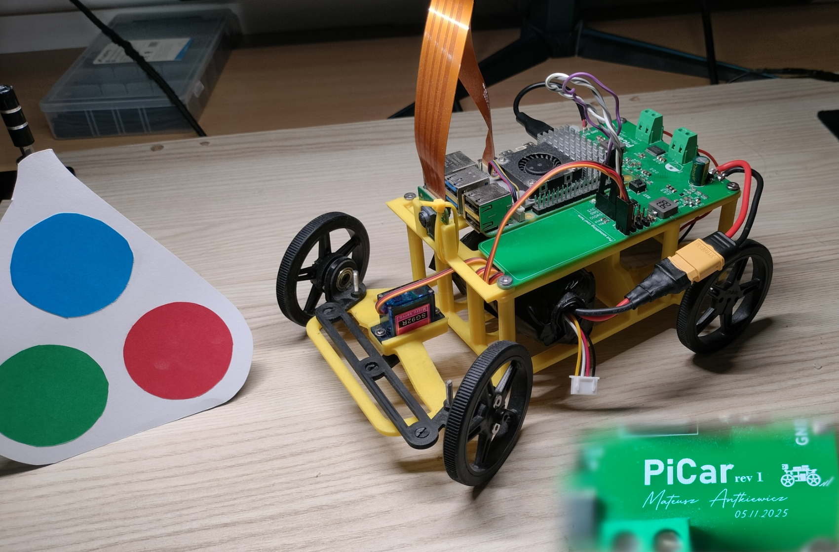
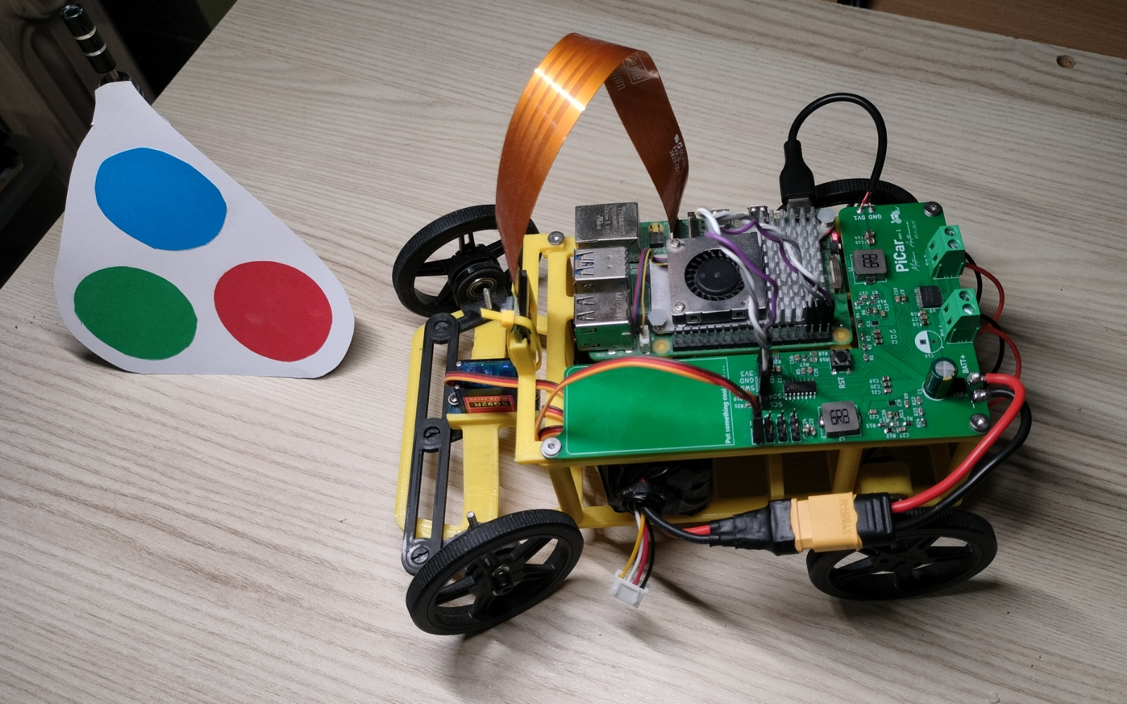
PiCar with the tracking marker next to it
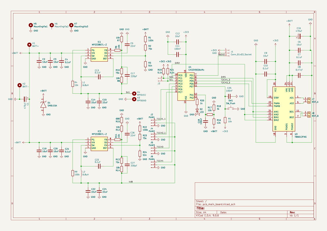
/pcb_main_board/pcb_main_board_schematic.svg
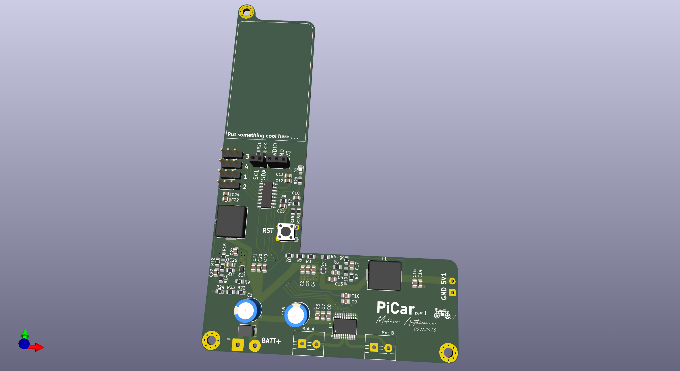
/images/pcb_main_board1.png
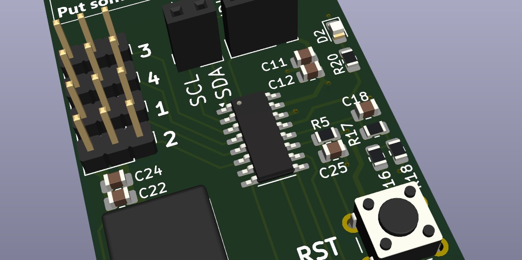
CH32V003 MCU is the main controller of the whole board. It is responsible for controlling the motor drivers, servo motors and monitoring the battery voltage. It communicates with the Raspberry Pi 5 over I2C.
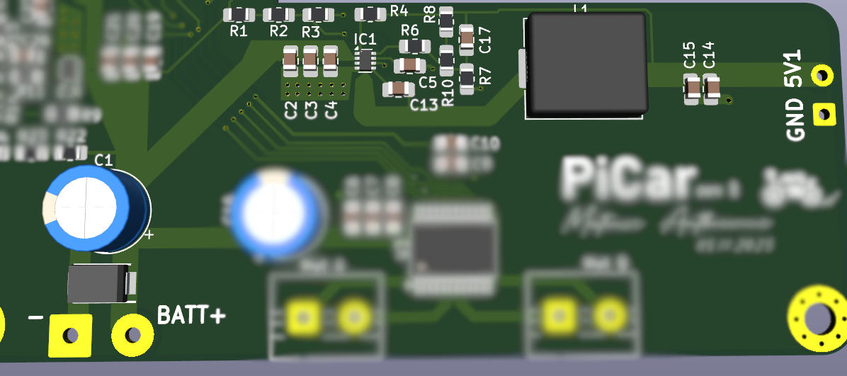
The battery input voltage is first filtered by the input low-ESR capacitor and capped to 15V by a SMBJ15A TVS diode. Then the MP2338 IC is used to reliably step-down the battery voltage from 9V-12.6V range to ~5.1V that is then connected via a USB-C cable to the RPi 5. The MP2338's GND pin is connected to wide copper traces with vias in order to improve cooling.
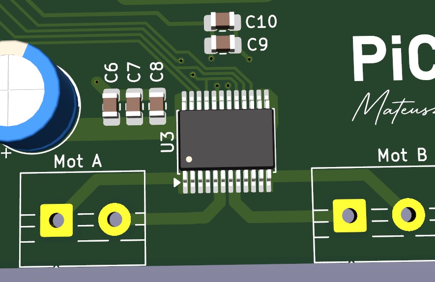
TB6612FNG IC is used to drive both of the main motors. The IC logic is driven by PWM signals generated by the on-board microcontroller. The PWM frequency can be adjusted from the software layer if the user wants to prioritize peak power or to minimize the audible switching noise. The lower the frequency, the more efficient the motors are, but the louder they become.
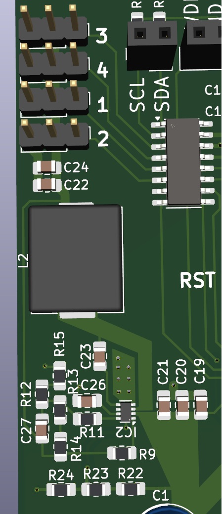
The mainboard is capable of running 4 separate hardware PWM signals at once which are generated by the on-board microcontroller. The servo motors are powered with 4.8V generated by another MP2238 IC configured in the same way as the other one used for powering RPi 5, except for the output voltage. The servo section also has a 3-pin header for each signal channel in order to simplify the connections. There are more servo channels than are currently needed for future-proofing reasons. e.g. allowing the camera to have adjustable yaw and pitch in the future.
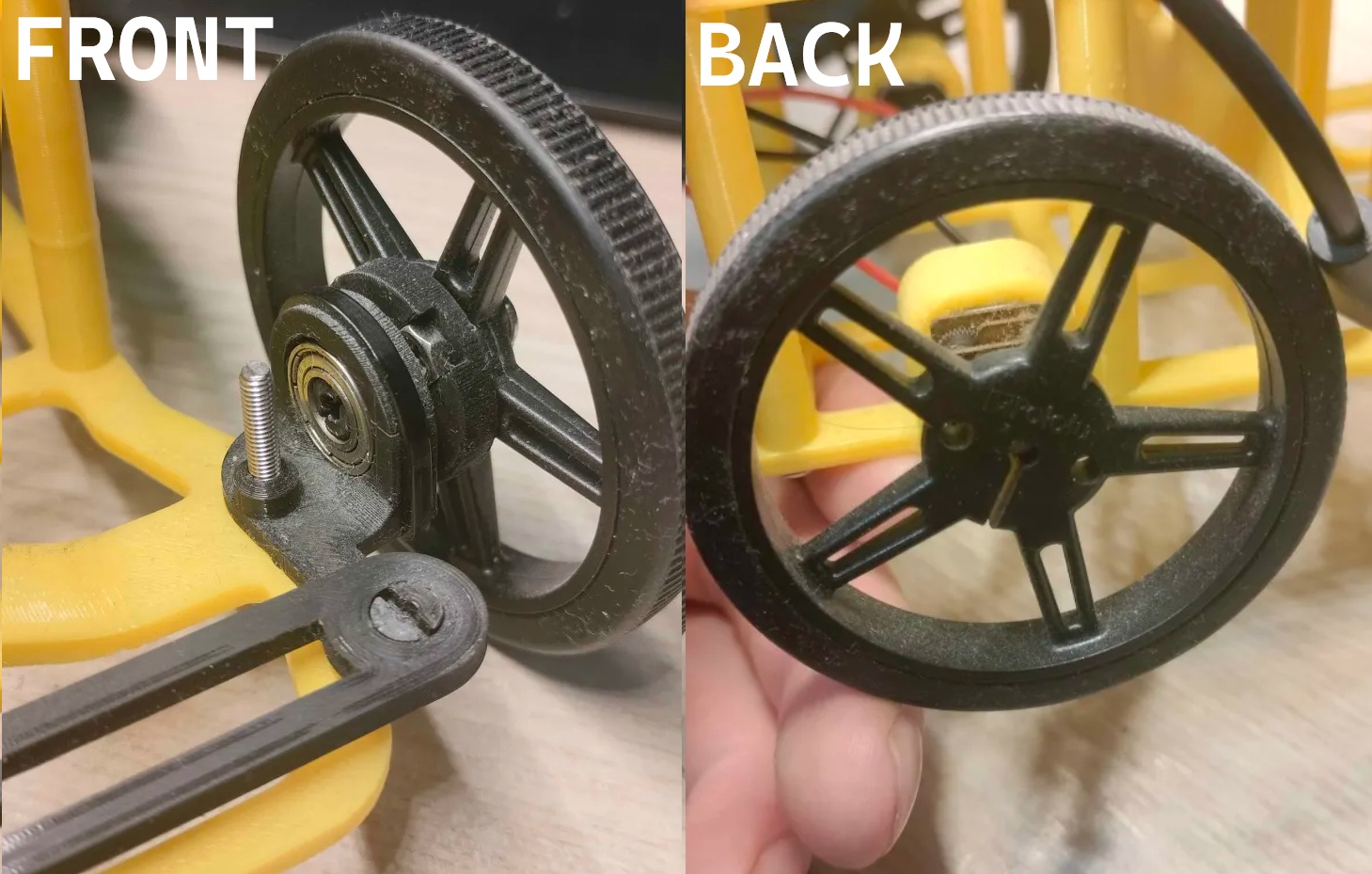
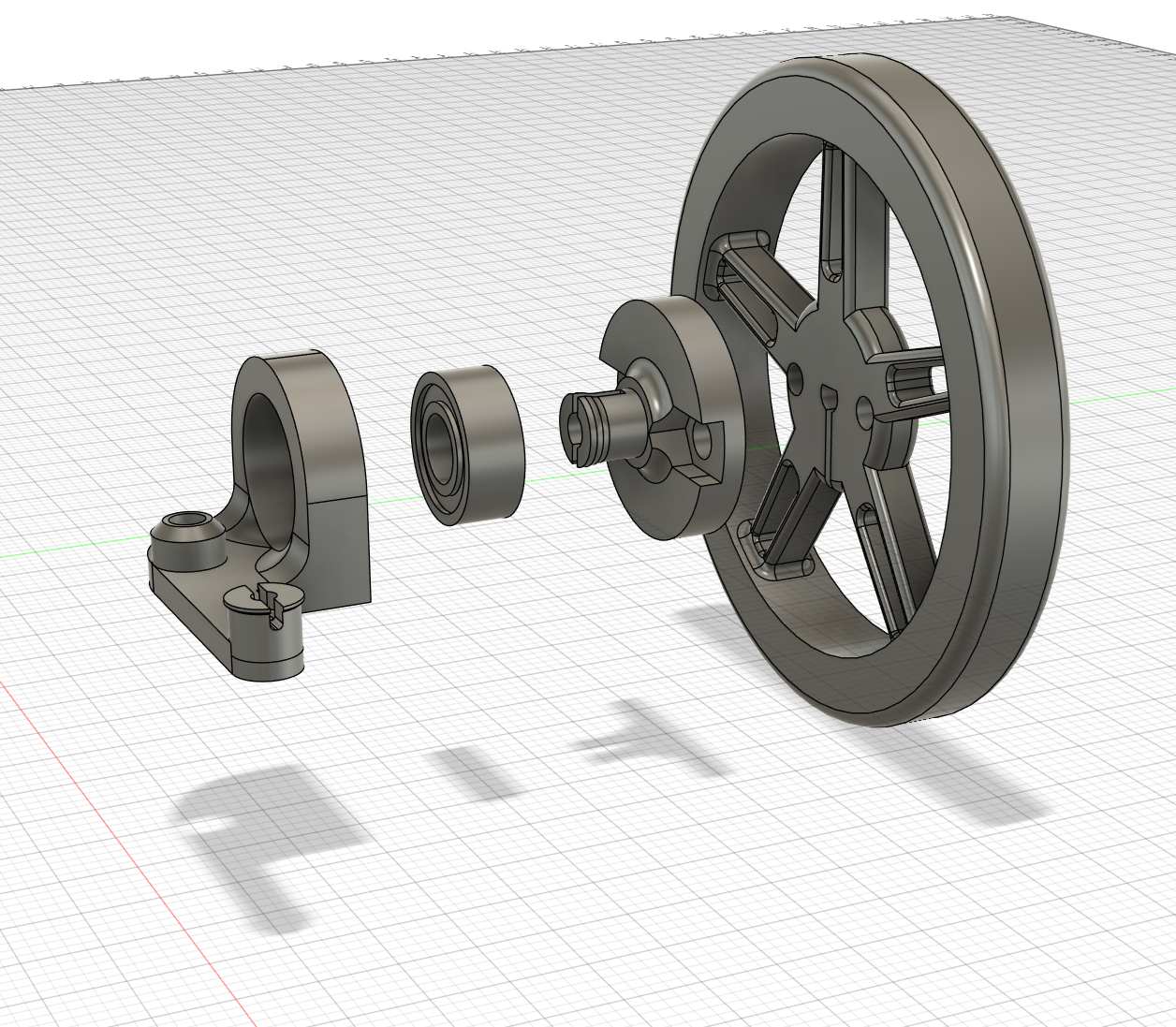
The front wheels are fastened to their mounts with short M3 screws. Those mounts then clip into the ball bearings, working similarly to LEGO Technic connections. A pin with the correct diameter and side cuts is pushed into the bearing hole and holds firmly enough for normal operation. The rear wheels are press-fitted onto the motor shafts:
Front wheel assembly disassembled in Fusion 360:
PiCar can be controlled through a simple Websockets-based web interface (/car/software/index.html). When you run the Python "Remote Control" main loop an HTTP server starts up and reveals the visual interface at http://{raspberry_pi_5_ip}:8000. There are two sliders that control it but the better (and way cooler) option is to use a gamepad and control the car this way. The website automatically detects connected gamepads and lets the user steer by using both triggers for accelerating and braking and the left thumbstick for steering. It is also possible to set the motors PWM switching frequency.
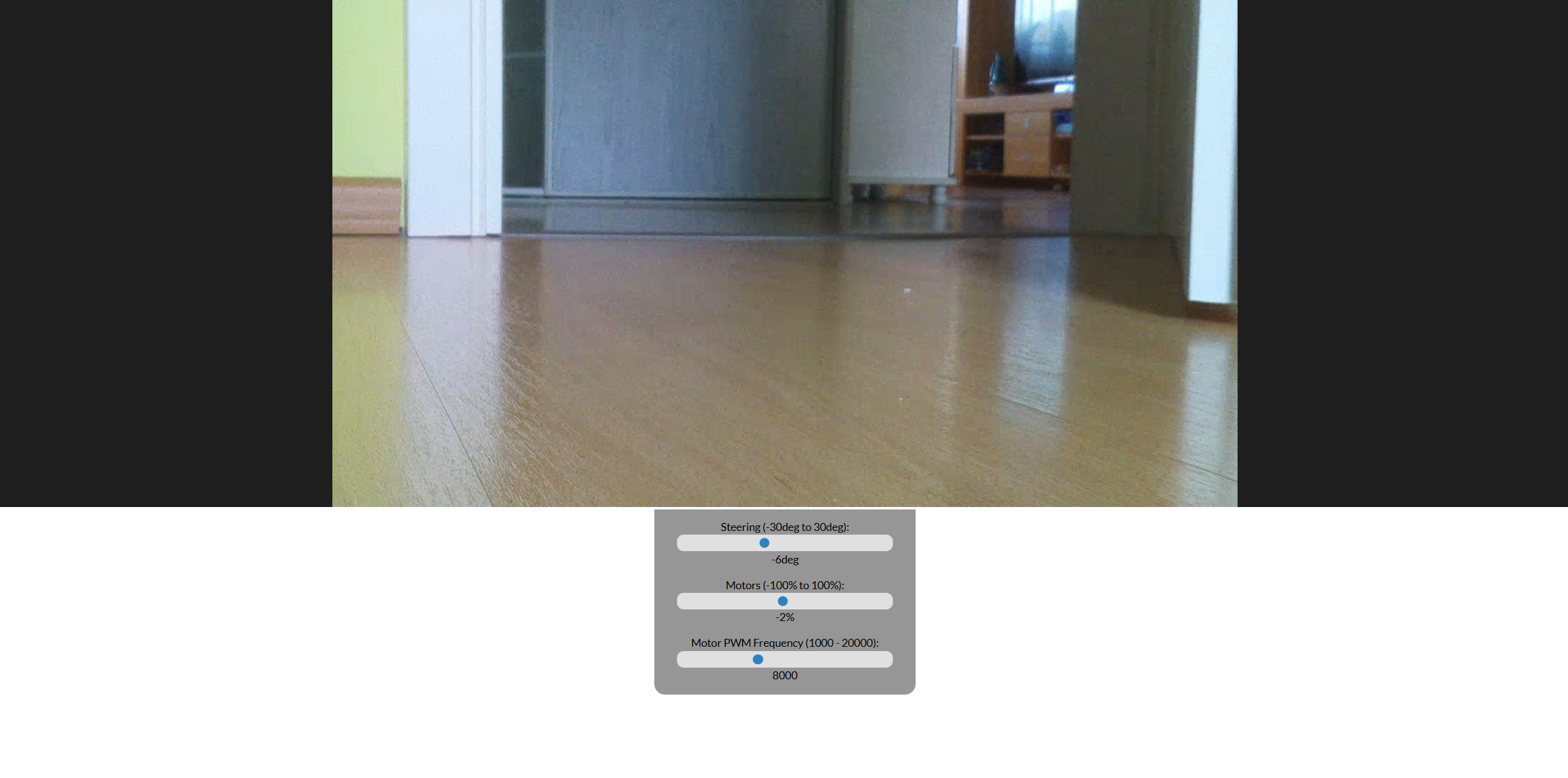
There also is a viewport for watching the live feed coming from the camera connected to the RPi 5. The stream source must be a WebRTC source which can be created easily by using MediaMTX. You can find the working mediamtx.yml file I use to enable the stream at /car/mediamtx.yml. Once mediamtx starts with my provided config, the camera can be accessed by connecting via WebRTC to {raspberry_pi_5_ip}:8889/rpi.
Autonomous driving, for now, is a simple computer vision algorithm that searches for a special marker with three key colors: red, green, and blue on the live feed streamed from the Raspberry Pi Camera HD v2 8MPx.
The camera feed is first filtered bilaterally to remove small details and noise in the subsequent marker search. Then gamma is adjusted to increase contrast, and the resulting image is binarized so that the SimpleBlobDetector from the OpenCV library can detect three circles. Finally, the algorithm checks whether the circles are "inside" the potentially found marker—i.e., whether they are not shifted from the averaged center by more than one standard deviation. If they are not, we can be certain that the marker has been found.
Below is a visualization of how the marker is seen by the algorithm:
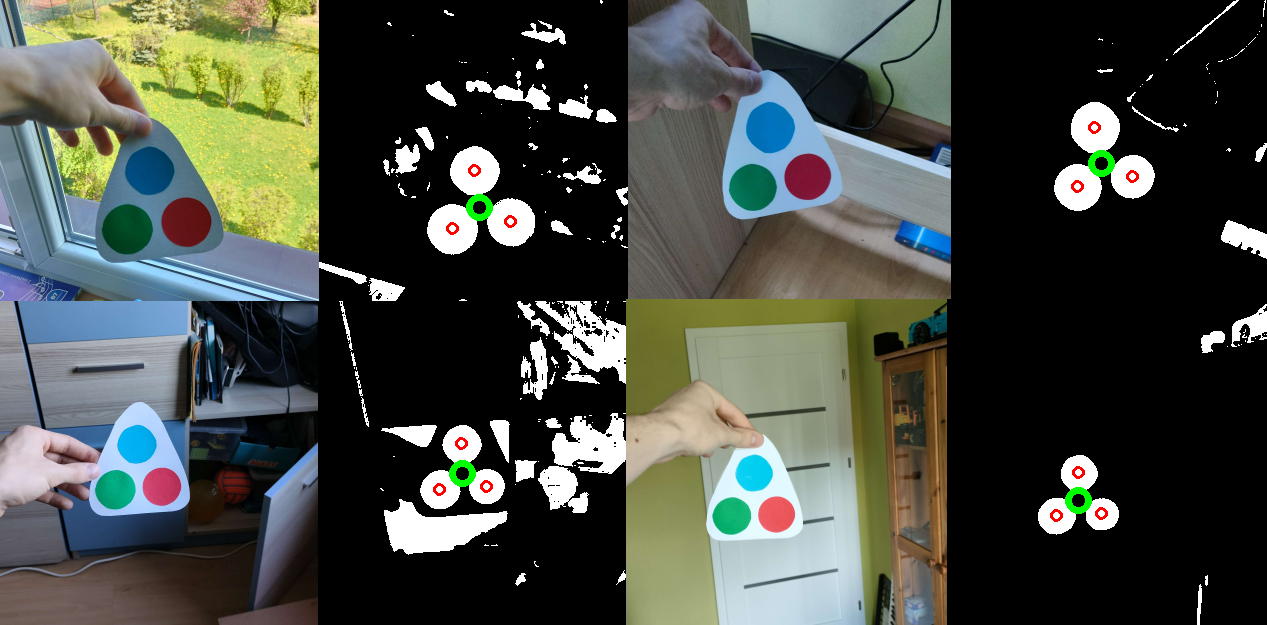
When the marker is found, the vehicle drives forward and turns so that the center of the marker aligns with the center of the camera's view. This is sufficient to effectively track the marker.
I plan to use a ToF distance sensor in tandem with the computer vision model DepthAnythingV2, which estimates depth using a single camera. This combination will allow me to acquire approximate (yet sufficiently accurate) distance information of everything visible in the front camera. This data will enable shape detection by contours and autonomous obstacle avoidance.
The CH32V003 microcontroller runs a firmware that acts as a PWM and motor control interface for the Raspberry Pi 5. The firmware exposes a register-based interface over I2C using slave address 0x17, allowing the RPi to elegantly control all aspects of motor and servo operation.
The firmware operates as an I2C slave that receives write-only commands structured as [register_id, data_low, data_high]. Each register controls a specific aspect of the system:
| Register | Purpose | Range |
|---|---|---|
| 1 | TIM1 (servo) frequency | 1 - 48000 Hz |
| 2 | TIM2 (motor) frequency | 1 - 48000 Hz |
| 4-7 | Servo CH1-CH4 duty cycle | 0 - PWM_PERIOD(1000) |
| 10-11 | Motor PWM (right/left) duty cycle | 0 - PWM_PERIOD(1000) |
| 12 | Motor direction control | Bit 0: DIRF, Bit 8: DIRB |
Configure the virtual environment if you need and run pip install -r requirements.txt while being in the /car/software directory to download the necessary packages. Downlaod opencv as a standalone package. Once everything is downloaded, run python main.py and it should work fine.
To make I2C communication work properly, enable it either with the raspi-config command or by manually adding the necessary lines to the /boot/firmware/config.txt file:
dtparam=i2c_arm=on
dtparam=i2c_arm_baudrate=80000 # or any other as you wish
dtparam=i2s=on
Also enable the camera detection in the same way. Here is the line for /boot/firmware/config.txt:
camera_auto_detect=1Downloading and building it through MounRiver Studio IDE is the easiest route to go. This repo already has project files that work out of the box when you open them with the IDE. Just press F7 and it should build perfectly fine.
You'll need a WCH LinkE programmer in order to flash the firmware to the chip. Once you have it, connect GND to GND and the SWDIO pin to the chip's SWIO pin according to its datasheet (It's pin PD1 for CH32V003A4M6). The chip must be powered either from the programmer's voltage pin or externally during flashing.
Now go to MounRiver Studio IDE and press F7 to build your project and then F8 to flash it having the WCH LinkE programmer plugged into your computer at the same time, note that flashing your code does not rebuild it automatically, you have to remember to press F7 each time.. You can also change the flashing configuration but it's almost always good to go by default. (called Download Configuration):
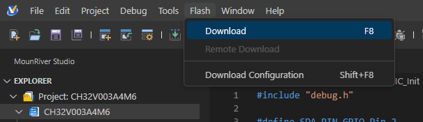
Do not press or hold the reset button during flashing (the NRST pin)
Take a look at the PROGRESS.md markdown file to see how the project evolved over time.
| Qty | Value | Footprint | References |
|---|---|---|---|
| 1 | 100n | Capacitor_SMD:C_0805_2012Metric | C2 |
| 1 | 10k | Resistor_SMD:R_0805_2012Metric | R1 |
| 1 | 10u | Capacitor_SMD:C_0805_2012Metric | C1 |
| 1 | CH32V003AxMx | Package_SO:SOP-16_3.9x9.9mm_P1.27mm | U1 |
| 1 | Conn_01x02_Socket | Connector_PinSocket_2.54mm:PinSocket_1x02_P2.54mm_Vertical | J3 |
| 1 | Conn_01x03_Socket | Connector_PinSocket_2.54mm:PinSocket_1x03_P2.54mm_Vertical | J1 |
| 1 | Conn_01x04_Pin | Connector_PinHeader_2.54mm:PinHeader_1x04_P2.54mm_Vertical | J5 |
| 1 | SW_Push | Button_Switch_THT:SW_PUSH_6mm | SW1 |
It measures 30 × 25 mm and has 2 copper layers, 1.6 mm thick.
8 parts. The full list of its parts is on this page, with links to each part's symbol and footprint where PCBKit's library has them.
From the ghemyn/picar repository on GitHub, at the commit this page was made from: the board is OLD_pwm_board/design/servo_controller.kicad_pcb and its schematic OLD_pwm_board/design/servo_controller.kicad_sch. PCBKit opens the board in the browser, with nothing to install.
Its repository publishes it under the MIT licence: you may reuse it on that licence's terms (keep the author's notice, and for a copyleft licence share your changes alike).
ghemyn/picar
Car with autonomous and remote-controlled capabilities using the Raspberry Pi 5

ghemyn/picar
Car with autonomous and remote-controlled capabilities using the Raspberry Pi 5


joeycastillo/Sensor-Watch
A board replacement for the classic Casio F-91W wristwatch

rusefi/rusefi
rusefi - GPL internal combustion engine control unit

hoglet67/RGBtoHDMI
Bare-metal Raspberry Pi project that provides pixel-perfect sampling of Retro Computer RGB/YUV video and conversion to HDMI

shanteacontrols/OpenDeck
A platform for building interactive control and sensing devices using MIDI and OSC built with Zephyr RTOS.

hackclub/OnBoard
💡 Join 1,000 teenagers and make your first PCB with a $100 grant!

dangiu/PicoMemcard
Emulating PSX Memory Card (or controller) using a Raspberry Pi Pico

OLIMEX/DIY-LAPTOP
Do It Yourself Open Source Hardware and Software Modular Hacker's Friendly Laptop