4 layers99.1 × 91.4 mm

 generationmake/ElaraGNSSMKRShield
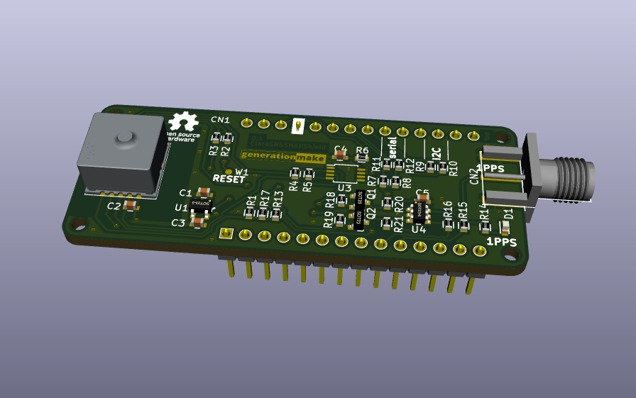
GNSS Shield with Wuerth Elara for Arduino MKR
ElaraGNSSMKRShield is an open-source printed circuit board by generationmake, from the generationmake/ElaraGNSSMKRShield repository on GitHub. It is a 2-layer board of 61.5 × 25 mm with 39 parts on 26 nets, routed with 310 tracks and 39 vias.
It is built around the SN74LVC2G34DBV, PCA9306D and TPS73618DBV, with the BSS138 and 150060GS75000 among its other parts. Its parts include 21 resistors, 5 capacitors, 4 ICs, 3 inductors and 2 transistors. It belongs with the radio and wireless boards of this library.


GNSS Shield with Wuerth Elara for Arduino MKR
| Pin | Pin Name | Signal | Description |
|---|---|---|---|
| 1 | AREF | ||
| 2 | DAC0/A0 | ||
| 3 | A1 | ||
| 4 | A2 | ||
| 5 | A3 | ||
| 6 | A4 | ||
| 7 | A5 | ||
| 8 | A6 | ||
| 9 | 0 | WAKE_UP | wake signal to Elara GNSS |
| 10 | 1 | 1PPS | 1PPS signal from Elara GNSS |
| 11 | 2 | ||
| 12 | 3 | ||
| 13 | 4 | ||
| 14 | 5 | ON_OFF | switch Elara GNSS on and off |
| 15 | 6 | ||
| 16 | 7 | ||
| 17 | 8/MOSI | ||
| 18 | 9/SCK | ||
| 19 | 10/MISO | ||
| 20 | 11/SDA | I2C_SDA | to Elara GNSS if I2C option is used |
| 21 | 12/SCL | I2C_SCL | to Elara GNSS if I2C option is used |
| 22 | 13/RX | SERIAL_RX | to Elara GNSS if serial option is used |
| 23 | 14/TX | SERIAL_TX | to Elara GNSS if serial option is used |
| 24 | RESET | ||
| 25 | GND | GND | |
| 26 | VCC | 3V3-rail | supply voltage for board |
| 27 | VIN | ||
| 28 | 5V0 |
SMA coax connector.
| Pin | Signal | Description |
|---|---|---|
| center | 1PPS | |
| shield | GND |
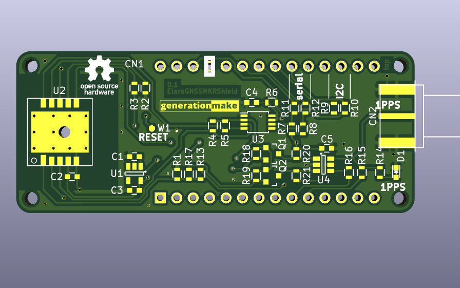
By default the Elara GNSS is connected via I2C. It is possible to connect to serial.
The following parts need to be changed:
| part | I2C variant | serial variant |
|---|---|---|
| R2 | 10k | DNI |
| R3 | DNI | 10k |
| R9 | 0R | DNI |
| R10 | 0R | DNI |
| R11 | DNI | 0R |
| R12 | DNI | 0R |
This hardware is licensed under the CERN OHL v. 1.2
| Qty | Value | Footprint | References |
|---|---|---|---|
| 7 | 10k | resistors:R_0603 | R1, R2, R13, R18, R19, R20, R21 |
| 6 | 0R | resistors:R_0603 | R9, R10, R11, R12, R15, R16 |
| 4 | 885012206095 | capacitors:C_0603 | C1, C2, C3, C5 |
| 4 | DNI | resistors:R_0603 | R3, R4, R5, R17 |
| 3 | 1k | resistors:R_0603 | R7, R8, R14 |
| 2 | BSS138 | SOT_TO:SOT-23 | Q1, Q2 |
| 1 | 150060GS75000 | LEDs:LED_0603 | D1 |
| 1 | 200k | resistors:R_0603 | R6 |
| 1 | 2613011037000 | RF_GPS:wuerth_WIRL-POSI_Elara-I | U2 |
| 1 | 60312202114509 | CON_wuerth:WR-SMA-PCB | CN2 |
| 1 | 885012206077 | capacitors:C_0603 | C4 |
| 1 | ARDUINO_MKR | MODULE_compute:ARDUINO_MKR_HOLES_PINHEADER_EDGE | CN1 |
| 1 | Label | Symbol:OSHW-Logo_5.7x6mm_SilkScreen | L3 |
| 1 | Label | labels:generationmake_logo | L2 |
| 1 | Label | labels:generationmake_small_solder | L1 |
| 1 | PCA9306 | SSOP:TSSOP-8_3x3mm_Pitch0.65mm | U3 |
| 1 | SN74LVC2G34 | SOT_TO:SOT-23-6 | U4 |
| 1 | TEST_1P | wire_pads:SolderWirePad_single_1mmSMD | W1 |
| 1 | TPS73618DBV | SOT_TO:SOT-23-5 | U1 |
It measures 61.5 × 25 mm and has 2 copper layers, 1.6 mm thick.
39 parts, built around the SN74LVC2G34DBV, PCA9306D, TPS73618DBV and BSS138. The full list of its parts is on this page, with links to each part's symbol and footprint where PCBKit's library has them.
From the generationmake/ElaraGNSSMKRShield repository on GitHub, at the commit this page was made from: the board is kicad_source/ElaraGNSSMKRShield.kicad_pcb. PCBKit opens the board in the browser, with nothing to install.
Its repository states no licence, so its author keeps all rights: ask generationmake before reusing the design.

EI9SP/Remote-Antenna-Switch
Four to one Remote Antenna Switch, Full duplex RS485


opulo-inc/example-autobom-project
example repo for testing autobom functionality


ad4363/LuX-ray-PCBs
A repository containing KiCad schematic and pcb files for a wireless radiation detector testing interface

NightLaneOrg/nr-si468x-dev
Si468x-based DAB/FM receiver module (M.2 E-Key) with open hardware and Linux integration.
