4 layers22 × 42 mm

 gcormier/serialsentinel3
Find out which serial ports the device has created.
Serialsentinel is an open-source printed circuit board by gcormier, from the gcormier/serialsentinel repository on GitHub. It is a 4-layer board of 82 × 68.9 mm with 72 parts on 114 nets, routed with 659 tracks and 286 vias.
It is built around the ESP32-C3-WROOM-02U-N4, CH382L and AMS1117-3.3, with the XC6206P182MR, MMBT3904 and SS54 among its other parts. Its parts include 20 capacitors, 20 resistors, 9 diodes, 8 connectors and 4 ICs. It belongs with the ESP32 and RISC-V boards of this library.


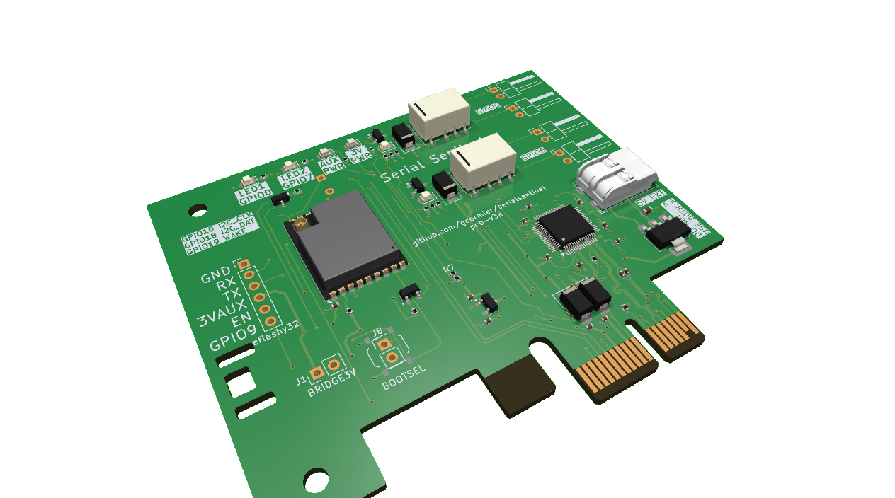
Allows you full control of your computer's power button and reset button, remotely. Exposes a serial power that lets you run a watchdog and restart your computer in the event of a lockup. Or, send commands to hard-reset, power on or power off whenever you'd like.
In a nutshell,
An external antenna can be attached carefully to the ESP32-C3 using a u.FL to SMA cable. Any standard 2.4GHz SMA antenna will work. You can either use the included cutouts on the PCB to zip tie the antenna, or 3D print a bracket, or use an old/existing bracket and drill a 1/4" (6.35mm) hole to fit the SMA side of the cable connector.
First, make sure you can see the device
$ lspci | grep CH382
03:00.0 Serial controller: Nanjing Qinheng Microelectronics Co., Ltd. CH352/CH382 PCI/PCIe Dual Port Serial Adapter (rev 10)
Find out which serial ports the device has created.
$ sudo dmesg | grep ttyS
[    0.496389] serial8250: ttyS1 at I/O 0x2f8 (irq = 3, base_baud = 115200) is a 16550A
[    0.498301] 0000:03:00.0: ttyS4 at I/O 0xd0c0 (irq = 17, base_baud = 115200) is a XR16850
[    0.500166] 0000:03:00.0: ttyS5 at I/O 0xd0c8 (irq = 17, base_baud = 115200) is a XR16850
In this case, ttyS4 and ttyS5 are the two serial ports. S4 is the native ESP32 serial port, which would be used for any logging or flashing over serial. S5 is the port you should use as communications for heartbeat and commands/etc based on the code you have running on the ESP32.
Sanity check that esptool can see and talk to the device.
$ esptool.py --port /dev/ttyS4 chip_id
esptool.py v4.8.1
Serial port /dev/ttyS4
Connecting....
Detecting chip type... ESP32-C3
Chip is ESP32-C3 (QFN32) (revision v0.4)
Features: WiFi, BLE
Crystal is 40MHz
MAC: b4:3a:45:4c:3f:f4
Uploading stub...
Running stub...
Stub running...
Warning: ESP32-C3 has no Chip ID. Reading MAC instead.
MAC: b4:3a:45:4c:3f:f4
Hard resetting via RTS pin...
If you see the above, you are ready to flash the firmware. If you don't see the device, check your serial port and ensure you have the right one.
Recommended baud rate is 115,200 for any flashing over serial.
Nope. You can use the device without any smarthome integration. It can be used as a standalone device to control your computer's power and reset buttons, and you can program it to do various tasks based on the serial commands it receives.
Nope. You can program the device to act on it's own based on the various inputs/conditions. You can do this with esphome, or with the Arduino framework or ESP-IDF. WiFi is only needed if you want to control the device remotely.
In theory you don't even need to use the serial ports (other then getting your code to the device). You could just flash esphome, and control the device yourself remotely. Or you could hardcode some dumb logic to control the power and reset buttons based on the inputs you have available.
More advanced usage would have you regularly sending a heartbeat to the device, and the device would then be able to reset your computer if it stops receiving heartbeats.
The circuit has logic that will reset the device via DTR/RTS so that the initial firmware can be loaded with esptool.
If your operating system is sending signals, that can cause the device to reset, or remain in a reset state
which would be an unresponsive state. You can try to prevent this with software. Or, after the first flash, you can remove the DTR/RTS jumpers on the PCB to prevent this from happening and keep updating the device over WiFi.
| Qty | Value | Footprint | References |
|---|---|---|---|
| 13 | 100n | Capacitor_SMD:C_0402_1005Metric | C3, C4, C5, C6, C7, C8, C9, C13, C213, C214, C215, C216, C217 |
| 12 | 1k | Resistor_SMD:R_0402_1005Metric | R1, R3, R7, R11, R13, R14, R15, R16, R17, R18, R19, R20 |
| 8 | 12K | Resistor_SMD:R_0402_1005Metric | R2, R4, R5, R6, R8, R10, R12, R206 |
| 4 | MMBT3904 | Package_TO_SOT_SMD:SOT-23 | Q2, Q3, Q4, Q5 |
| 4 | Red | LED_SMD:LED_0805_2012Metric | D3, D4, D6, D7 |
| 4 | SS54 | Diode_SMD:D_SMA | D1, D2, D8, D9 |
| 3 | 10u | Capacitor_SMD:C_0402_1005Metric | C11, C12, C14 |
| 3 | 1u | Capacitor_SMD:C_0402_1005Metric | C1, C2, C15 |
| 2 | G6K-2F-Y DC3 | Relay_SMD:Relay_DPDT_Omron_G6K-2F-Y | K2, K3 |
| 1 | 22u | Capacitor_SMD:C_0603_1608Metric | C10 |
| 1 | 5VEXT | Connector_PinHeader_2.54mm:PinHeader_1x02_P2.54mm_Vertical | J9 |
| 1 | AMS1117-3.3 | Package_TO_SOT_SMD:SOT-223-3_TabPin2 | U4 |
| 1 | BOOTSEL | Connector_PinHeader_2.54mm:PinHeader_1x02_P2.54mm_Vertical | J8 |
| 1 | Bus_PCI_Express_x1 | Connector_PCBEdge:BUS_PCIexpress_x1 | J2 |
| 1 | Buzzer | Buzzer_Beeper:MagneticBuzzer_PUI_AT-0927-TT-6-R | BZ1 |
| 1 | CH382L | Package_QFP:LQFP-64_7x7mm_P0.4mm | U1 |
| 1 | DTR | Connector_PinHeader_2.54mm:PinHeader_1x02_P2.54mm_Vertical | J3 |
| 1 | ESP32-C3-WROOM-02U | RF_Module:ESP32-C3-WROOM-02U | U3 |
| 1 | Green | LED_SMD:LED_0805_2012Metric | D10 |
| 1 | RELAY1 | Connector_PinHeader_2.54mm:PinHeader_1x05_P2.54mm_Horizontal | J5 |
| 1 | RELAY2 | Connector_PinHeader_2.54mm:PinHeader_1x05_P2.54mm_Horizontal | J6 |
| 1 | RESET | Button_Switch_SMD:SW_Push_1P1T_XKB_TS-1187A | SW1 |
| 1 | RP3V | Jumper:SolderJumper-2_P1.3mm_Open_RoundedPad1.0x1.5mm | JP5 |
| 1 | RP3VAUX | Jumper:SolderJumper-2_P1.3mm_Open_RoundedPad1.0x1.5mm | JP4 |
| 1 | RTS | Connector_PinHeader_2.54mm:PinHeader_1x02_P2.54mm_Vertical | J4 |
| 1 | WAKE | Jumper:SolderJumper-2_P1.3mm_Bridged_RoundedPad1.0x1.5mm | JP1 |
| 1 | XC6206P182MR | Package_TO_SOT_SMD:SOT-23-3 | U2 |
| 1 | eflashy32 | Connector_PinHeader_2.54mm:PinHeader_1x06_P2.54mm_Vertical | J7 |
It measures 82 × 68.9 mm and has 4 copper layers, 1.61 mm thick.
72 parts, built around the ESP32-C3-WROOM-02U-N4, CH382L, AMS1117-3.3 and XC6206P182MR. The full list of its parts is on this page, with links to each part's symbol and footprint where PCBKit's library has them.
From the gcormier/serialsentinel repository on GitHub, at the commit this page was made from: the board is pcb/serialsentinel.kicad_pcb and its schematic pcb/serialsentinel.kicad_sch. PCBKit opens the board in the browser, with nothing to install.
Its repository states no licence, so its author keeps all rights: ask gcormier before reusing the design.

justinlindh/digits
Encrypted retro phone network — private VoIP over vintage desk phones


ilomon10/embedded-totalizer-hour-meter
ESP32 engine hour meter & totalizer: firmware, SensorFrame protocol, Node host tools, KiCad PCB and a Deno device simulator


hicancan/carbentra-smart-plug
CARBENTRA smart plug: AIoT edge device for campus energy orchestration

rekirxs/NeoXalle-PCB-Slave
A full PCB work for a sport sensorial reaction device called NeoXalle.