
2 layers200.4 × 251.2 mm

 gatekeep/KFDToolSW_NET4.03
Quick test to see feasibility to downgrade the KFDTool GUI to .NET 4.0
KVLShield is an open-source printed circuit board by gatekeep, from the gatekeep/KFDToolSW_NET4.0 repository on GitHub, published under the MIT licence. It is a 2-layer board of 68.6 × 53.3 mm with 134 parts on 41 nets, routed with 164 tracks and 11 vias.
It is built around the MMBT3904LT1G. Its parts include 12 resistors, 11 connectors, 5 diodes, 4 switches and 2 transistors.
A fork of the amazing KFDTool software for an Arduino, plus schematics and board files for a shield.
Completed shields can be purchased from the online store
Note: You must use the build of the KFDTool software attached to this GitHub repo in order for your homebrew adapter to work. The stock KFDTool software will not find your Arduino.
Currently, the following boards have been tested and confirmed to work:
The following boards should work, however have not been tested:
The following boards have been reported to work with minor modifications:
Further testing and problem reporting by the community is encouraged to further improve compatibility with other devices.
Setup consists of three parts.
The hardware for the KFD-AVR fork is very simple. You can either purchase a KFDShield from the online store, or build your own circuit on a breadboard. The bare minimum you need to get going is this:
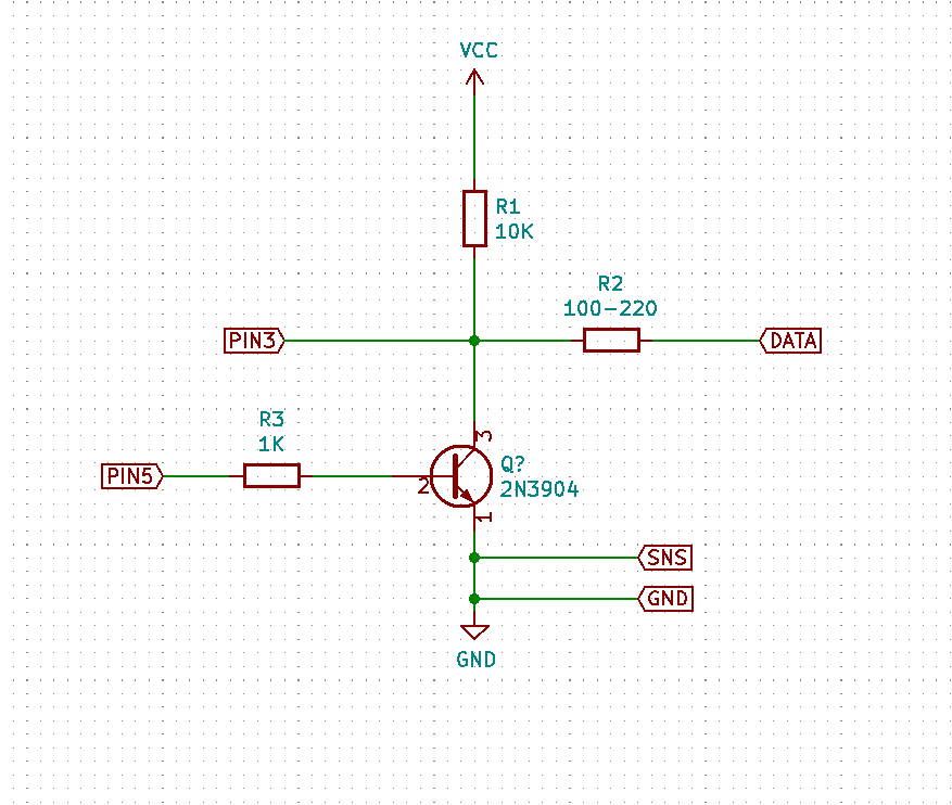
Where PIN3 is Arduino pin 3, PIN5 is Arduino pin 5, DATA is the radio data line, SNS, is the radio sense line, and GND is the radio ground line. VCC is 5 volts (make sure you are using a 5 volt tolerant board).
If you are using a shield, on the TRS connector, tip is data, ring is sense, and shield is ground.
Head to the Releases page and download both the Firmware and Software zips from the latest version. Save the software for later. Unzip Firmware, and open the kfd-avr.ino file in the Arduino IDE, and select your board type and COM port from the Tools menu. If you are using a board that is not explicitly supported, or DIYing your own rather than using a shield, you should confirm that all options in the hal.h file are correct - namely, CPU speed and data/LED pins. Once you are done, hit upload.
The software distributed with the KFD-AVR release is "flat pack", meaning there is no installer supplied - all you need to do to run the software is unzip the Software zip and run the KFDToolGui.exe file. You may see an "Error - timeout while waiting for data" when first opening the software. This is completely normal, especially if you have many COM ports on your system. The warning will be suppressed in a future release. Select the COM port corresponding to your Arduino, and you should see information populate in the bottom bar of the screen indicating that the KFDTool software is connecting to your Arduino.
In order to validate that every part of the chain - hardware, firmware, and software - is working, go to the Utility - Adapter Self Test menu, and click "Detect MR". This will send a signal to your radio asking it to reply and confirm it is there. If you get a success message, congrats! You are ready to load keys.
Open Source P25 Key Fill Device
Compliant with P25 standards (TIA-102.AACD-A)
Purchase Hardware: online store
Download Software: latest release
Release Notifications: subscribe
Demonstration: video
Software Manual: view
Security Considerations: view
Key Fill Device (KFD)
The KFDtool software supports KFD features through the KFDtool hardware adapter (TWI/3WI/Three Wire Interface), as well as through a IP (UDP) connection (DLI/Data Link Independent interface).
Keys and groups of keys can be saved to an AES-256 encrypted key container file, which can then be selected and loaded into a target device in one operation.
Supported Manual Rekeying Features (TIA-102.AACD-A)
Motorola refers to the P25 standard 3 wire interface (3WI) keyload protocol as ASTRO 25 mode or CKR mode.
The legacy Motorola proprietary keyloading formats SECURENET and ASN (Advanced SECURENET) are NOT supported by KFDtool. PID mode is also used to refer to ASN mode.
Key validators/generators are available for the following algorithms:
Mobile Radio (MR) Emulator
The KFDtool software only supports MR Emulator features through the KFDtool hardware adapter (TWI/3WI/Three Wire Interface) at this time.
This mode allows another keyloader to be connected to the KFDtool, and the keys retrieved.
Supported Manual Rekeying Features (TIA-102.AACD-A)
Any statements of compatibility do not imply endorsement by the vendor. Testing has not been performed by the vendor themselves.
A detailed list of compatible radios and adapters is available here.
Radios that are compatible with Motorola KVL3000/KVL3000+/KVL4000/KVL5000 keyloaders in ASTRO 25 mode should be compatible with KFDtool.
Keyloading cables made for other radios with MX (Motorola KVL) connectors can be modified by soldering an AC101 or AC102 Hirose pigtail in parallel with the MX connector according to these instructions.
Operations encapsulated with encryption (commonly referred to as FIPS mode) are not supported at this time for either the KFD or MR emulation modes.
Assembled and tested KFDtool hardware is available from me directly. I can ship internationally. Please visit the online store to place an order.
Proceeds from hardware sales enables me to further develop the software.
| Part Number | Description |
|---|---|
| KFD100 | Single Hirose port USB key fill device (includes 1 m / 3 ft USB A to USB B cable) |
| AC100 | 6 pin male plug Hirose to 6 pin male plug Hirose cable (0.5 m / 1.5 ft) |
| AC101 | 6 pin male plug Hirose pigtail for custom cables (0.5 m / 1.5 ft) |
| AC102 | 6 pin female jack Hirose pigtail for custom cables (0.5 m / 1.5 ft) |
| AC103 | Motorola R2670 compatible adapter (0.15 m / 6 in) |
| AC104 | Kenwood KPG-115 compatible adapter (0.15 m / 6 in) |
| AC105 | 4 way female jack passive Hirose splitter |
| AC106 | Kenwood KPG-93 compatible adapter (0.15 m / 6 in) |
| AC107 | Motorola XTS4000 compatible adapter (0.15 m / 6 in) |
| AC108 | Aeroflex/IFR 2975 compatible adapter (0.15 m / 6 in) |
| AC109 | Harris XG-100P/XL-150P/XL-185P/XL-200P compatible adapter |
KFDtool software supports 32-bit and 64-bit Windows 7, Windows 8.1, and Windows 10
The .NET Framework 4.7.2 or later compatible must be installed
The use of a virtual machine with USB passthrough is NOT supported at this time
KFDtool software, firmware, and hardware is distributed under the MIT License (see LICENSE.txt).
KFDtool is a trademark of Florida Computer and Networking, Inc.
All product names, trademarks, registered trademarks, logos, and brands are property of their respective owners. All company, product, and service names used are for identification purposes only. Use of these names, trademarks, logos, and brands does not imply endorsement.
Note about hardware:
I request that no one else manufactures identical or compatible units and sells them to others while I am still doing so - I have put quite a bit of my own money into developing this hardware. I am totally fine with someone making a unit for themselves or a couple of extras to give to their friends, just that they don't charge for them. Proceeds from hardware sales enables me to further develop the software.
Included open-source components:
Software (see doc/SW_LICENSE.txt):
Firmware (see doc/FW_LICENSE.txt):
| Qty | Value | Footprint | References |
|---|---|---|---|
| 100 | SolderWire-0.5sqmm_1x01_D0.9mm_OD2.1mm | Connector_Wire:SolderWire-0.5sqmm_1x01_D0.9mm_OD2.1mm | , , , , , , , , , , , , , , , +84 |
| 5 | 10K | Resistor_SMD:R_0603_1608Metric | R1, R4, R10, R11, R12 |
| 4 | CONN_01X01 | Socket_Arduino_Uno:Arduino_1pin | P5, P6, P7, P8 |
| 3 | 470 | Resistor_SMD:R_0603_1608Metric | R7, R8, R9 |
| 2 | 1K | Resistor_SMD:R_0603_1608Metric | R3, R6 |
| 2 | 220 | Resistor_SMD:R_0603_1608Metric | R2, R5 |
| 2 | D_Zener | Diode_SMD:D_SOD-323F | D1, D2 |
| 2 | MMBT3904LT1G | Package_TO_SOT_SMD:SOT-23 | Q1, Q2 |
| 1 | ACT | LED_SMD:LED_0603_1608Metric | D4 |
| 1 | Analog | Socket_Arduino_Uno:Socket_Strip_Arduino_1x06 | P2 |
| 1 | Digital | Socket_Arduino_Uno:Socket_Strip_Arduino_1x08 | P4 |
| 1 | Digital | Socket_Arduino_Uno:Socket_Strip_Arduino_1x10 | P3 |
| 1 | Down | Button_Switch_SMD:SW_SPST_CK_RS282G05A3 | SW3 |
| 1 | Enter | Button_Switch_SMD:SW_SPST_CK_RS282G05A3 | SW4 |
| 1 | MR_Block | Connector_Phoenix_MC:PhoenixContact_MC_1,5_3-G-3.5_1x03_P3.50mm_Horizontal | J1 |
| 1 | MR_Jack | Connector_Audio:Jack_3.5mm_PJ320D_Horizontal | J3 |
| 1 | OLED | Connector_PinSocket_2.54mm:PinSocket_1x04_P2.54mm_Vertical | J2 |
| 1 | PWR | LED_SMD:LED_0603_1608Metric | D3 |
| 1 | Power | Socket_Arduino_Uno:Socket_Strip_Arduino_1x08 | P1 |
| 1 | SNS | LED_SMD:LED_0603_1608Metric | D5 |
| 1 | SW_Push | Button_Switch_SMD:SW_Push_1P1T_NO_6x6mm_H9.5mm | SW1 |
| 1 | Up | Button_Switch_SMD:SW_SPST_CK_RS282G05A3 | SW2 |
It measures 68.6 × 53.3 mm and has 2 copper layers, 1.6 mm thick.
134 parts, built around the MMBT3904LT1G. The full list of its parts is on this page, with links to each part's symbol and footprint where PCBKit's library has them.
From the gatekeep/KFDToolSW_NET4.0 repository on GitHub, at the commit this page was made from: the board is hw/KFDShield/KVLShield.kicad_pcb. PCBKit opens the board in the browser, with nothing to install.
Its repository publishes it under the MIT licence: you may reuse it on that licence's terms (keep the author's notice, and for a copyleft licence share your changes alike).

antmicro/com-express-7-baseboard
This project contains open hardware design files for a baseboard supporting COM Express 7 modules. The board breaks-out major communications and peripheral interfaces provided by the standard.

nuerolynx/embedded-systems-lab
Arduino UNO R4 WiFi and ESP32 prototypes for access control, automation, displays, monitoring, and Bluetooth audio.

kins-dev/igrill-smoker
Using the iGrill as a control unit for a DIY smoker

zarlicho/Qris-soundbox-esp32
QRIS Soundbox adalah sistem notifikasi pembayaran realtime yang dikembangkan untuk menerima dan memproses notifikasi pembayaran QRIS melalui protokol MQTT.


sergeyvfx/GPSDOMonitor
A tiny module which is connecting to a databus of GPSDO modules with the goal to visualize when the PLL is locked, GPS time is stabilized and things like this.