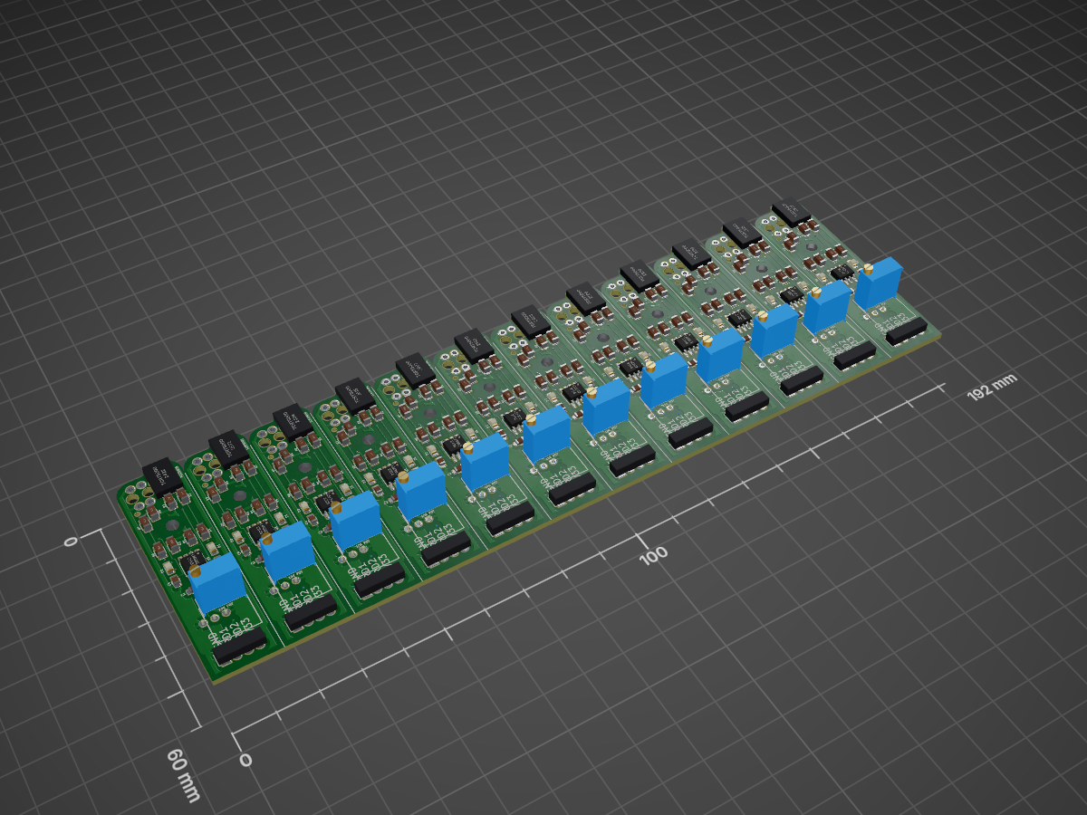

GOLReader RevA Panel12
Game of Light Installation
- Size
- 192 × 60 mm
- Copper layers
- 2
- Thickness
- 1.6 mm
- Parts
- 252
- Nets
- 12
- Pads
- 732
- Tracks, vias
- 2,506, 240
- Pours
- 60
- Routed
- Yes
- KiCad
- KiCad 4
- Created
- 8 Feb 2017
- Updated
- 7 Apr 2019
Overview
GOLReader RevA Panel12 is an open-source printed circuit board by gatechipdl, from the gatechipdl/GameOfLight repository on GitHub, published under the MIT licence. It is a 2-layer board of 192 × 60 mm with 252 parts on 12 nets, routed with 2,506 tracks and 240 vias.
It is built around the TCRT5000 and LM393. Its parts include 96 resistors, 48 capacitors, 36 ICs, 24 diodes and 12 connectors.
Main components
2README
README.mdGameOfLight
Game of Light Installation
Requirements
- 36 stations
- each station 1m in lenght covered in leds
- 5 sections of lamp to create a 'species'
- automatic identification of each lamp 'species'
Location
- Hyatt Regency Denver at Co Convention Center
Main Power Supply
- 12,24V power supply recommended with a buck converter (for leds and mcu) or linear regulator (if for just mcu) at each location
- typical computer psu will have several 12V rails. A modular psu would be best for ensuring enough 12V rails without extra wiring.
- if there is 5m of leds with 30 leds/meter wrapped around a tube, then that is 150 leds. 150 leds at 60mA is 9A running at around 3V. This is around 27-30W assuming an efficient local conversion of power, which is likely embedded within the addressable chip.
- 36 stations of 30W is a total max draw of 1080W. So a 800W-1000W-1200W power supply should be fine.
Local Power Regulation
- Switch mode power supply for high current, such as this 300W Step Down Regulator
- Linear regulator for low current needs (eg. if using 12V main power supply and 12V leds)
Power Distribution Connectors
- ribbon cable (40 pin), using most pins for power and ground
- RJ45 can only handle up to 1A
- RJ11 can only handle up to 1A
- 5557 molex need to crimp; not designed to be removed often;
- DC Barrel Jack 5.5mm, most connectors designed for 3A, but can get special ones for laptaps that can handle 8A
- 6 pin Pluggable Screw Terminal
- 12V - GND - DataMinus - DataPlus - GND - 12V
- 7 pin Pluggable Screw Terminal
- 12V - GND - DataMinus - GND - DataPlus - GND - 12V
- extra ground in middle is for connecting ground to the main controller in the case that the main controller is not using the same ground as the stations' ground from the main power supply. For example if the main controller is run by or powered by a laptop.
Power Distribution Wiring
- $27 100 ft. 14/2 White Solid SIMpull NM-B Wire
- $38 100 ft. 14-2 Black Stranded Landscape Lighting Cable
- $16 100' Feet 14 Gauge Red Black Stranded 2 Conductor Speaker Wire Car Home Audio Ga
- $26 eXtreme Products 2 Conductor 14 Gauge Stranded Copper Core Speaker Wire (No Aluminum Core) for Home Theater Speakers Radio Speakers Car Audio or Any Audio Interface - 100 Foot Clear Coat
Signal Distribution Wiring
- for RS485 we need overall impedance of 120 ohms. For our distances, lighter gauges are fine, but this recommends 24AWG or heavier. Here are more recommendations.
- Two wire or Three wire. May need three wire to include an additional ground in the case that the main controller is not using the same ground as the stations' power ground from the main power supply. This could be the case with a laptop for example.
- $13 Ethernet Cable (100 Feet), cut and pull out twisted pair wires
- $23 100-Feet 24-Gauge 4 Pair Cat 5e
LEDs
- addressable color leds
- could use 1 2m strip folded over
- could use 1 5m strip wrapped around a pole (this will provide more light)
- WS2811 with 3 color leds on each section, each led is rgb, but in clusters of 3. This is fine for our applications. Also these are 12V, which is better for current draw. $8-10 per 5m strip
Control
- recommended individual controller for each station; otherwise refresh rate is likely to be very slow
- attiny85 possible? may not have enough pins; but might
- atmega328p?
- arduino pro mini clone ($1-2)
- 1 master device with 36 other devices. The master controls the CA simulation and dictates the animation colors and patterns to each of the 36 stations.
- however, it is possible to have the 36 devices run the simulation themselves, with each device getting data about it's neighbors, and computing the next step and selecting it's own animation. This would also require that they all synchronize, to some degree on an update algorithm. This could be done. Would be really nice to have. This is something we could first develop in the master/slave configuration, and then later spend time developing the slave-only method if there is time. The slave-only would really connect conceptually rather than having any kind of single master.
Recognition
- manual input (what a drag)
- infrared linear quadrature encoder or similar to recognize the lamp 'species' as a barcode when the lamp shade is slide over the rod
- this would argue for a separate controller on each station
- IR Distance Sensor
Communication
- if using multiple controllers, one on each station, using a multidrop bus rather than a shift/ring topology
- I2C can go about 20ft without additional driver or buffers
- RS-232 can go about 50ft
- RS-422 can go about 5000ft, but is single driver/master, and up to 10 receivers. It is differential, so it's more noise immune than rs232, but the primary downside is it is one directional communcation
- RS-485 can go about 4000ft
- RS-485 to ttl converter using the MAX485CSA
- $0.38 Module
- needs twisted pair wire (same as RS422); actually can go without twisted pair if run is shorter, so this isn't completely necessary
- downside is that RS485 supports up to 32 devices. But I don't think that is built into the protocol. We should be able to go over that. As each device will have it's own way of identifying itself. I think 32 devices is more of a guideline.
- RS-485 might need a 3.3V version like the SP3485 Module. This board is lower cost than if we were to purchase just the chip and integrate it into our own design.
Parts
252| Qty | Value | Footprint | References |
|---|---|---|---|
| 48 | 10K | Resistors_SMD:R_1206 | R2, R2, R2, R2, R2, R2, R2, R2, R2, R2, R2, R2, R3, R3, R3, R3 +32 |
| 48 | 1K | Resistors_SMD:R_1206 | R1, R1, R1, R1, R1, R1, R1, R1, R1, R1, R1, R1, R4, R4, R4, R4 +32 |
| 36 | 0.1uF | Capacitors_SMD:C_0805 | C2, C2, C2, C2, C2, C2, C2, C2, C2, C2, C2, C2, C3, C3, C3, C3 +20 |
| 24 | 10K POT | Potentiometers:Potentiometer_Bourns_3296W_3-8Zoll_Inline_ScrewUp | RV1, RV1, RV1, RV1, RV1, RV1, RV1, RV1, RV1, RV1, RV1, RV1, RV2, RV2, RV2, RV2 +8 |
| 24 | LED | LEDs:LED-0805 | D1, D1, D1, D1, D1, D1, D1, D1, D1, D1, D1, D1, D2, D2, D2, D2 +8 |
| 24 | TCRT5000 | MyKiCadParts:TCRT5000 | U1, U1, U1, U1, U1, U1, U1, U1, U1, U1, U1, U1, U2, U2, U2, U2 +8 |
| 12 | 10uF | Capacitors_SMD:C_1206 | C1, C1, C1, C1, C1, C1, C1, C1, C1, C1, C1, C1 |
| 12 | CONN_01X04 | Pin_Headers:Pin_Header_Straight_1x04 | P1, P1, P1, P1, P1, P1, P1, P1, P1, P1, P1, P1 |
| 12 | LM393 | Housings_SOIC:SOIC-8_3.9x4.9mm_Pitch1.27mm | U3, U3, U3, U3, U3, U3, U3, U3, U3, U3, U3, U3 |
The 240 most common of 252 parts.
More from gatechipdl/GameOfLight
6- 2 layers70 × 70 mm

- 2 layers70 × 70 mm

- 2 layers

- 2 layers16 × 60 mm

- 2 layers114.3 × 96.5 mm

- 2 layers63.5 × 35.6 mm

Similar boards
- 2 layers66.4 × 52.5 mm

- 2 layers135.8 × 56.1 mm

Power board
xtarke/automated_buggy
This shield connects microcontroller (MSP-EXP430FR2355) pins to the car's power board. Go to Power Board for more hardware information.
87 parts5GPL-3.0 - 2 layers103 × 80 mm

EduRoMAA EduCIAA
ciiiutnfrc/eduromaa
Versión educativa del robot móvil RoMAA (EduRoMAA)
81 parts3GPL-3.0 - 2 layers106.7 × 26.7 mm

IrDetectieBoard
TiebeDeclercq/Munt-sorteer--en-opslagsysteem
A coin-counting, storing, and dispensing system. View the blog »
75 parts - 2 layers200 × 78.8 mm

Openridingcontroller rev2
Squalius-cephalus/OpenRidingController
D.I.Y horse riding controller for the PC.
30 parts13 - 2 layers160 × 42 mm

ESP kicad2
Amrlxyz/esp-lfr-buggy
2nd Year Embedded Systems Project (ESP) - Line Following Robot Buggy
28 parts4 - 2 layers34.1 × 108.8 mm

- 2 layers150 × 100 mm

Maze kiCad
billtsol/Maze
This project demonstrates how to use an Arduino board, IR sensors, and a motor driver shield to create a maze-solving robot.
39 parts2
Questions
How big is the GOLReader RevA Panel12 PCB?
It measures 192 × 60 mm and has 2 copper layers, 1.6 mm thick.
What parts does the GOLReader RevA Panel12 use?
252 parts, built around the TCRT5000 and LM393. The full list of its parts is on this page, with links to each part's symbol and footprint where PCBKit's library has them.
Where can I download the GOLReader RevA Panel12 KiCad files?
From the gatechipdl/GameOfLight repository on GitHub, at the commit this page was made from: the board is electronics/GOLReader_RevA-Panel12/GOLReader_RevA-Panel12.kicad_pcb. PCBKit opens the board in the browser, with nothing to install.
Can I use the GOLReader RevA Panel12 design in my own project?
Its repository publishes it under the MIT licence: you may reuse it on that licence's terms (keep the author's notice, and for a copyleft licence share your changes alike).