4 layers43.2 × 62 mm
USBAudioBridge
fsodari/USBAudioBridge
NXP RT1010 based USB to I2S bridge to connect to a Digilent Arty A7.
120 parts

 garvita4/split-keyboard
This is a custom spli keybaord with the 1.8inch tft diaply and rotatory encoder and also with nfc based lock system with the controlable backlight .
Splitkeybaord is an open-source printed circuit board by garvita4, from the garvita4/split-keyboard repository on GitHub. It is a 2-layer board of 335.7 × 101 mm with 251 parts on 196 nets, routed with 3,177 tracks and 550 vias.
It is built around the ESP32-S3-WROOM-1-N4R8, ME6211A33M3G-N and TP4056, with the 1N4148WS, KT-0603W and AO3400A among its other parts. Its parts include 84 diodes, 68 resistors, 50 switches, 20 capacitors and 6 ICs. It belongs with the ESP32 boards of this library.


This is a custom spli keybaord with the 1.8inch tft diaply and rotatory encoder and also with nfc based lock system with the controlable backlight . This keyboard can be used as wired keybaord as well as the wireless keybaord with the 2 bluetooth profile
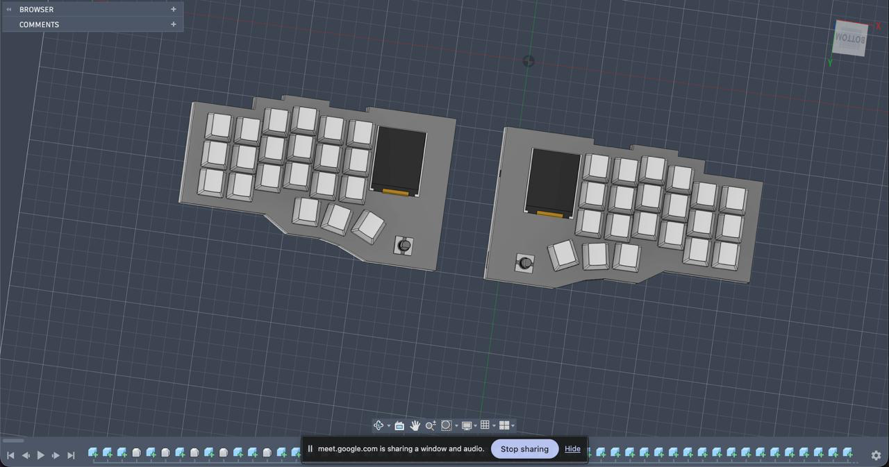
Two separate keyboard halves, each built around its own ESP32-S3 microcontroller and supporting electronics.
Each side having 21 MX switches and with the backlight.
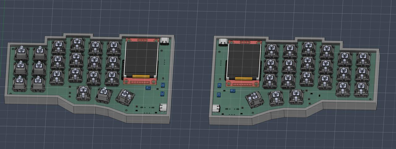
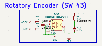
EC11 rotary encoders provide physical controls for functions such as volume and brightness.
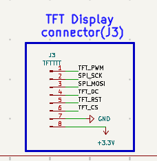
Two 1.8-inch TFT displays are included for displaying system information such as battery percentage and connectivity status. Can also play animation on idle state.
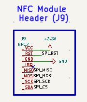
RC522 readers provide the hardware for RFID card detection and card-based interactions used to unlock the keyboard or the PC depend on the firmware either use it as the keyboard lock or use it to open the pc via your nfc tag or the phone nfc
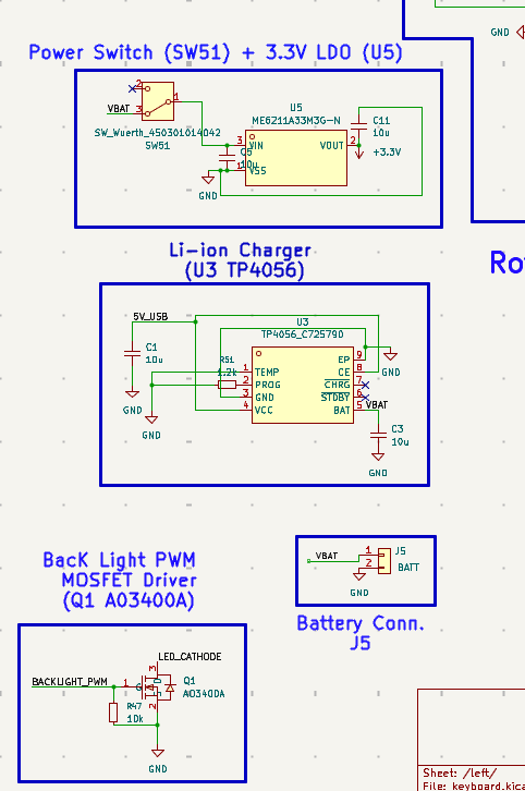
Each half has a rechargeable 10000 mah LiPo battery witht he inbuilt BMS which power up the whole half and can provide long lasting backup on the bluetooth mode .
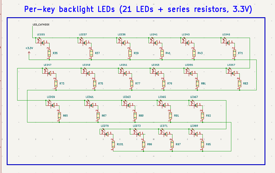
White 0805 SMD LEDs are use to work as the backlight like professional keybaord with the intensity control uc an control the backlight intensity with the same rotatory encoder
The switch matrix connects the mechanical switches to the microcontroller. Diodes help prevent unwanted electrical paths during simultaneous key presses.
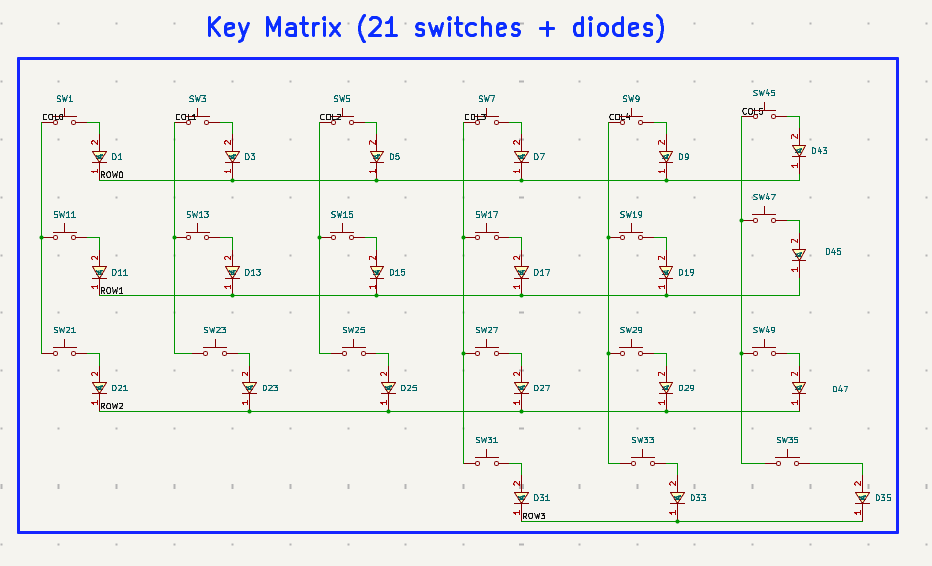
Mechanical switches provide individual key inputs, while 1N4148WS diodes support switch-matrix isolation.
Resistors support the associated circuits, while white SMD LEDs provide per-key backlighting.
The ESP32-S3-WROOM-1-N4R8 acts as the main controller for each keyboard half.
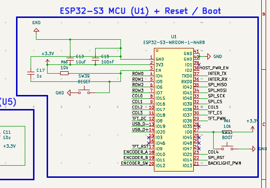
The EC11 encoders provide rotation and switch inputs for additional keyboard controls.
The display connections allow the ESP32-S3 to communicate with the TFT modules.
The RC522 reader connections provide the interface for RFID card detection.
The power circuit includes LiPo battery charging, 3.3 V regulation, MOSFET switching, and resettable overcurrent protection.
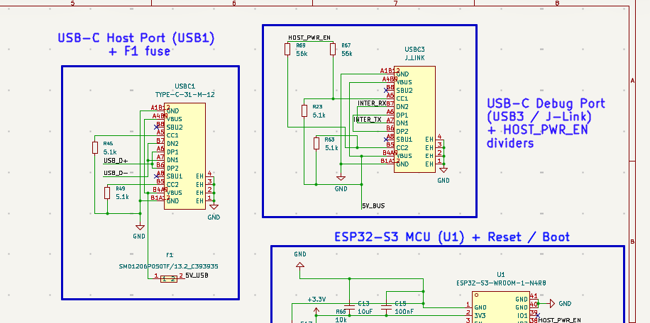
USB-C connectors provide the interfaces intended for charging, firmware uploading, and supported wired connections.
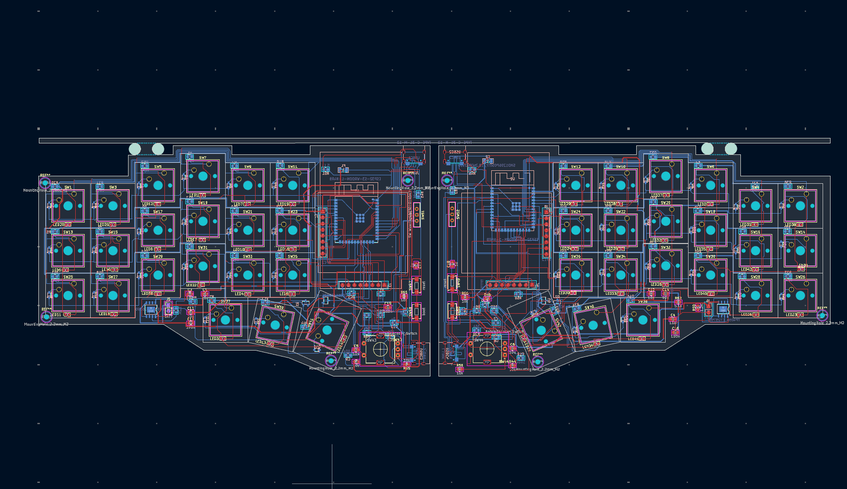
The custom schematic and PCB layout were designed in KiCad, with the boards manufactured by Zbotic. The PCB integrates the keyboard matrix, controller connections, peripheral interfaces, backlighting, and power circuitry.
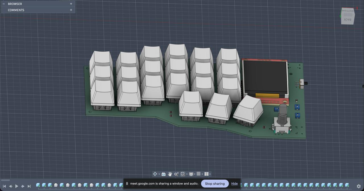
The keyboard enclosure is modelled in Fusion 360 to accommodate the custom PCB, switches, displays, rotary encoders, and internal electronics.
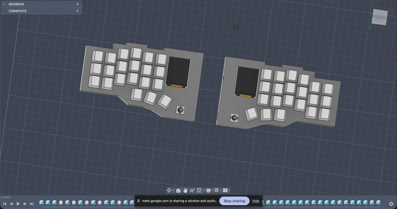
The firmware is implemented using the Arduino framework and PlatformIO for the ESP32-S3 microcontrollers. It enables wireless communication between the two halves of the split keyboard using ESP-NOW, while the left half acts as the primary Bluetooth HID device.
The firmware scans the 4 × 6 key matrix, detects key presses and releases, and maps them to keyboard characters. The left half sends keystrokes to the connected device over Bluetooth Low Energy (BLE), while the right half transmits key events wirelessly to the left half.
The implementation uses the BleKeyboard library for Bluetooth keyboard functionality and ESP-NOW for communication between the two halves. The current firmware provides the foundation for the keyboard's core input functionality and can be extended with additional key mappings, layers, and peripheral integrations.
The following table lists the components required to build the REIKAI split mechanical keyboard, including specifications, quantities, estimated costs, and sourcing links.
| Category | Component | Qty | Specifications | Unit Price (INR) | Total (INR) | Unit Price (USD) | Total (USD) | Source |
|---|---|---|---|---|---|---|---|---|
| Processing & Communications | ESP32-S3-WROOM-1 | 2 | Dual-core, Wi-Fi/BLE, 16MB Flash, 8MB PSRAM | ₹569.00 | ₹1,138.00 | $6.0324 | $12.06 | Robu |
| Processing & Communications | RC522 Mini NFC Module | 2 | Mini PCB, SPI interface | ₹139.00 | ₹278.00 | $1.4736 | $2.95 | Indian Hobby Center |
| Processing & Communications | 1.8" TFT Display | 2 | SPI interface, ST7735 | ₹309.00 | ₹618.00 | $3.2759 | $6.55 | Robu |
| Inputs & Key Matrix | MX Mechanical Switches | 42 | Cherry MX2A, ₹391 per pack of 10 | ₹39.10 | ₹1,642.20 | $0.4145 | $17.41 | Meckeys |
| Inputs & Key Matrix | Switch Diodes | 42 | 1N4148WS, SOD-323 | ₹1.09 | ₹45.78 | $0.0116 | $0.49 | Sunrom |
| Inputs & Key Matrix | EC11 Rotary Encoder | 2 | 5-pin, through-hole, push button | ₹58.00 | ₹116.00 | $0.6149 | $1.23 | Robu |
| Illumination | 0805 White LEDs | 42 | SMD backlight LEDs | ₹0.58 | ₹24.36 | $0.0061 | $0.26 | KTRON |
| Illumination | AO3400A N-Channel MOSFET | 2 | SOT-23, LED PWM dimming | ₹6.00 | ₹12.00 | $0.0636 | $0.13 | Robu |
| Power & Connectivity | USB Type-C Receptacle | 4 | 16-pin SMD connector | ₹5.55 | ₹22.20 | $0.0588 | $0.24 | KTRON |
| Power & Connectivity | 10,000 mAh LiPo Battery | 2 | Single-cell, 3.7V–4.2V | ₹399.00 | ₹798.00 | $4.2301 | $8.46 | MakerBazar |
| Power & Connectivity | TP4056 IC | 2 | SOP-8, LiPo charger | ₹5.05 | ₹10.10 | $0.0535 | $0.11 | KTRON |
| Power & Connectivity | ME6211A33M3G IC | 2 | SOT-23-5, 3.3V LDO regulator | ₹8.00 | ₹16.00 | $0.0848 | $0.17 | Robu |
| Power & Connectivity | Resettable PTC Fuse | 2 | 1206, 500mA | ₹9.00 | ₹18.00 | $0.0954 | $0.19 | Robu |
| Power & Connectivity | SMD Push Switches | 4 | 3×4×2.5mm, BOOT/EN | ₹4.29 | ₹17.16 | $0.0455 | $0.18 | Robu |
| Power & Connectivity | Slide Switch | 2 | SPDT, battery disconnect | ₹2.70 | ₹5.40 | $0.0286 | $0.06 | Robu |
| Supporting Passives | 100Ω Resistor | 42 | 0805 SMD, LED current limiting | ₹0.30 | ₹12.60 | $0.0032 | $0.13 | KTRON |
| Supporting Passives | 10kΩ Resistor | 12 | 0805 SMD, pull-up/pull-down | ₹0.30 | ₹3.60 | $0.0032 | $0.04 | KTRON |
| Supporting Passives | 56kΩ Resistor | 4 | 0805 SMD, HOST_PWR_EN divider | ₹0.30 | ₹1.20 | $0.0032 | $0.01 | KTRON |
| Supporting Passives | 5.1kΩ Resistor | 4 | 0805 SMD, HOST_PWR_EN divider | ₹0.30 | ₹1.20 | $0.0032 | $0.01 | KTRON |
| Supporting Passives | 1.2kΩ Resistor | 2 | 0805 SMD, TP4056 PROG pin | ₹0.30 | ₹0.60 | $0.0032 | $0.01 | KTRON |
| Supporting Passives | 10µF Capacitor | 10 | 0805 SMD, decoupling | ₹7.98 | ₹79.80 | $0.0846 | $0.85 | KTRON |
| Supporting Passives | 1µF Capacitor | 2 | 0805 SMD, power filtering | ₹8.50 | ₹17.00 | $0.0901 | $0.18 | KTRON |
| Supporting Passives | 100nF Capacitor | 8 | 0805 SMD, noise decoupling | ₹1.00 | ₹8.00 | $0.0106 | $0.08 | KTRON |
| PCB | Custom PCB | 1 | Custom-designed PCB fabrication | ₹4,243.50 | ₹4,243.50 | $45.00 | $45.00 | Zbotic |
| Description | Amount |
|---|---|
| Grand Total (INR) | ₹9,128.80 |
| Grand Total (USD) | $96.80 |
| Qty | Value | Footprint | References |
|---|---|---|---|
| 42 | 0805 | Resistor_SMD:R_0805_2012Metric | R1, R2, R10, R11, R12, R13, R14, R15, R16, R17, R18, R19, R20, R21, R22, R23 +26 |
| 42 | 1N4148WS T4 | easyeda2kicad:SOD-323_L1.8-W1.3-LS2.5-RD | D1, D2, D10, D11, D12, D13, D14, D15, D16, D17, D18, D19, D20, D21, D22, D23 +26 |
| 42 | BL | easyeda2kicad:LED0603-R-RD_WHITE | LED1, LED2, LED10, LED11, LED12, LED13, LED14, LED15, LED16, LED17, LED18, LED19, LED20, LED21, LED22, LED23 +26 |
| 40 | SW_Push | Button_Switch_Keyboard:SW_Cherry_MX_1.00u_PCB | SW1, SW2, SW10, SW11, SW12, SW13, SW14, SW15, SW16, SW17, SW18, SW19, SW20, SW21, SW22, SW23 +24 |
| 12 | 10k | Resistor_SMD:R_0805_2012Metric | R43, R44, R47, R48, R55, R56, R57, R58, R59, R60, R65, R66 |
| 8 | 100n | Capacitor_SMD:C_0805_2012Metric | C7, C8, C9, C10, C15, C16, C19, C20 |
| 8 | 10u | Capacitor_SMD:C_0805_2012Metric | C1, C2, C5, C6, C11, C12, C13, C14 |
| 8 | 5.1k | Resistor_SMD:R_0805_2012Metric | R45, R46, R51, R52, R61, R62, R63, R64 |
| 4 | 56k | Resistor_SMD:R_0805_2012Metric | R67, R68, R69, R70 |
| 2 | 1.2K | Resistor_SMD:R_0805_2012Metric | R49, R50 |
| 2 | 10U | Capacitor_SMD:C_0805_2012Metric | C3, C4 |
| 2 | 1u | Capacitor_SMD:C_0805_2012Metric | C17, C18 |
| 2 | AO3400A | easyeda2kicad:SOT-23-3_L2.9-W1.3-P1.90-LS2.4-BR | Q1, Q2 |
| 2 | BATT | Connector_PinHeader_2.54mm:PinHeader_1x02_P2.54mm_Vertical | J5, J6 |
| 2 | ESP32-S3-WROOM-1-N4R8 | easyeda2kicad:WIRELM-SMD_ESP32-S3-WROOM-1 | U1, U2 |
| 2 | J_LINK | easyeda2kicad:USB-C_SMD-TYPE-C-31-M-12_1 | USBC3, USBC4 |
| 2 | ME6211A33M3G-N | easyeda2kicad:SOT-23-3_L2.9-W1.6-P1.90-LS2.8-BR | U5, U6 |
| 2 | NFC2 | Connector_PinHeader_2.54mm:PinHeader_1x08_P2.54mm_Vertical | J7, J8 |
| 2 | RotaryEncoder_Switch | Rotary_Encoder:RotaryEncoder_Alps_EC11E-Switch_Vertical_H20mm | SW43, SW44 |
| 2 | SMD1206P050TF/13.2_C393935 | easyeda2kicad:F1206 | F1, F2 |
| 2 | SW_Push | Button_Switch_Keyboard:SW_Cherry_MX_1.50u_PCB | SW41, SW42 |
| 2 | SW_Wuerth_450301014042 | Button_Switch_THT:SW_Slide-03_Wuerth-WS-SLTV_10x2.5x6.4_P2.54mm | SW51, SW52 |
| 2 | TFTTT | Connector_PinHeader_2.54mm:PinHeader_1x08_P2.54mm_Vertical | J3, J4 |
| 2 | TP4056_C725790 | easyeda2kicad:ESOP-8_L4.9-W3.9-P1.27-LS6.0-BL-EP | U3, U4 |
| 2 | TYPE-C-31-M-12 | easyeda2kicad:USB-C_SMD-TYPE-C-31-M-12_1 | USBC1, USBC2 |
| 2 | VAL** | Panelization:mouse-bite-5mm-slot | mouse-bite-5mm-slot, mouse-bite-5mm-slot |
| 2 | boot | Button_Switch_SMD:SW_SPST_EVQPE1 | SW48, SW50 |
| 2 | reset | Button_Switch_SMD:SW_SPST_EVQPE1 | SW47, SW49 |
The 244 most common of 251 parts.
It measures 335.7 × 101 mm and has 2 copper layers, 1.6 mm thick.
251 parts, built around the ESP32-S3-WROOM-1-N4R8, ME6211A33M3G-N, TP4056 and 1N4148WS. The full list of its parts is on this page, with links to each part's symbol and footprint where PCBKit's library has them.
From the garvita4/split-keyboard repository on GitHub, at the commit this page was made from: the board is PCB/splitkeybaord.kicad_pcb and its schematic PCB/splitkeybaord.kicad_sch. PCBKit opens the board in the browser, with nothing to install.
Its repository states no licence, so its author keeps all rights: ask garvita4 before reusing the design.
fsodari/USBAudioBridge
NXP RT1010 based USB to I2S bridge to connect to a Digilent Arty A7.

JohnNeville/SunSprout
An esp32-c5 powered board that adds dual source battery charging, fuel management, and differential i2c bus. This was largely developed to be a complement with my other soil sensor project.

zgeez/Pixel-Badge
Wearable 32x32 LED badge with Zephyr firmware, BLE control, passive NFC, and a Flutter Android app, built around a custom nRF52840 PCB.

DennisRathgeb/doppler-radar-detector
24 GHz CW Doppler + FMCW radar detector: STM32F429 + ESP32 + TouchGFX live UI, CMSIS-DSP FFT, FastAPI backend, YOLOv8 angle-of-arrival sensor fusion desktop app. ZHAW PM4 team project.


ADVecu/ADV.dash
ADV.dash is a dashboard project built with LVGL and ESP32-S3. It is prepared to receive CAN bus data from rusEFI and, in the future, other programmable ECUs.


hpvdt/typhoon_motherboard
Folder for each of the boards designed for a given project, even if there is only one board for a given project.