
2 layers555.6 × 69 mm
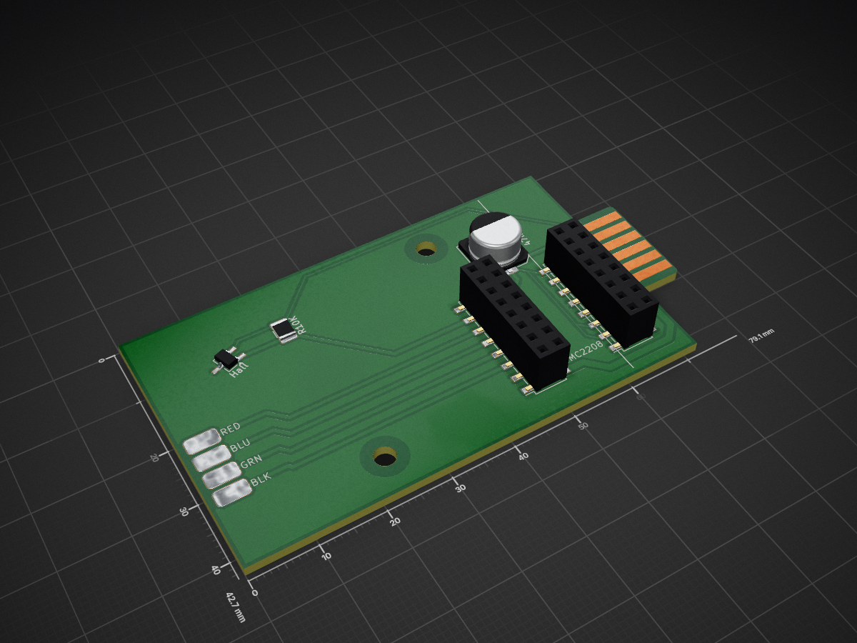
Split Flap Display
Module is an open-source printed circuit board by g000ze, from the g000ze/Split-Flap-Display repository on GitHub, published under the Apache-2.0 licence. It is a 2-layer board of 79.1 × 42.7 mm with 14 parts on 11 nets, routed with 53 tracks and 0 vias.
It belongs with the lEDs and displays boards of this library.
Older people (like me) look back with nostalgia at train stations and airports, middle-aged people are captivated by technology, and the younger generation is excited by the clattering sound combined with the non-virtual movement. The split flap display remains a fascinating display panel for text and small animations.
One day, while watching a video about split flap displays, I suddenly felt the desire to own one. After a relatively short research, I realized that only a few manufacturers build such displays. There are, for example, Oat Foundry, Vestaboard, Scott Bezek or the one called "Split Flap Display Manufacturer." No matter which manufacturer you choose, the displays are either very expensive or don't meet my requirements. So I decided to try building one myself.

A typical split flap display looks best when it can display text. This text is naturally composed of characters, i.e., letters, numbers, and special characters. Optionally, symbols, colors, or images can also be displayed. A character is represented on the display by a so-called module. A module consists of a housing, a stepper motor, a motor driver, a PCB that connects the driver and the motor, a carousel, 50 flaps for the characters, and, of course, various spacers and screws that hold the whole thing together. A magnetic sensor (Hall effect sensor) is also integrated into the carousel, which tells the microprocessor when position 0 or the home position has been reached.
As already mentioned, a single module produces little effect, so we want multiple modules for a display to achieve an intense visual effect. I decided to control eight modules with an Arduino Micro. The modules therefore always come in units of eight. The Micro offers 20 digital input/output pins. Two of these are required per module: an output pin as a stepper for the driver and an input pin for the Hall effect sensor to determine the feedback for a full rotation of the carousel. This means a total of 16 Arduino pins are used for eight modules. The Arduino, in turn, is placed on the backplane PCB, where the modules are plugged into so-called card edge connectors. This PCB primarily controls two things:
Animation of spinning spool using OpenSCAD
The housing is used to position the motor, along with the carousel and flaps, as well as the PCB with the Hall sensor. If everything is exactly right, the flaps will drop at the right time and the magnet will move correctly over the sensor. I used 0.8 mm sheet steel for the housing. The 3D OpenSCAD drawing can be found here. I found a company in Switzerland called Blexon, that will punch and bend the housing according to my specifications.
Normally, Nema 17 stepper motors are mounted on the side where the shaft is located. This display is different; the motor must be mounted on one side, and the shaft, where the carousel is screwed to, must be on the opposite side. The 17HS13-0404D is the only Nema 17 I could find with the shaft on the opposite side from where it is mounted. This motor is actually a "dual shaft" motor. The 17HS13-0404D is powered by +12 volts.
To operate a stepper motor, you need a driver. There are many. I experimented with stepper motor drivers for a long time until I finally came across the TMC2208 "Silent Step Stick" from Watterott. This driver allows the 17HS13-0404D to run almost silently. Finally, the sound of a split-flap display plays a crucial role. We want to hear only the flaps clattering, not the motors.
Two different types of PCBs are required. One is a small PCB that is attached to each module. It essentially carries the driver and the Hall sensor. The other is the backplane PCB, which connects the Arduino's electronic wires to the eight modules via card-edge connectors. The six connections that run via the card-edge connectors are:
The TMC2208 and the Hall sensor on the module PCB each operate at +5 VCC, while the motor naturally requires 12 volts.
The Carousel is attached to the pouley on the motor shaft so that it can be rotated by the steppermotor. It also holds the 50 flaps in position. The stepper motor is located inside the carousel. With its 82mm diameter, the carousel fits perfectly around the motor and there's enough space for the 50 flap positions. The two wheels are different, as the left wheel contains spokes, while the right wheel is open.
I decided to use 3mm PVC plates for the carousel. A company named Waterjet located in Switzerland did the water cutting to cut out the carousel wheels.
The pouley connects the motor and the carousel together. This one was actually the only one I found to suit the motor shaft. So I bought it, even though it is insanely overpriced.
The flaps are the essential parts, since they show the text that you want to see. Basically almost all kind of fonts, characters, signs and pictures are possible. After endless searching, trying and disapointments, I found a company named Ren Peck in China who was willing to create what I am looking for. In fact it is the very same company that created the flaps for Scott Bezeks Split Flap Display.
One flap has basically the size of 40mm height and 50mm width. There are two little notches on each side in order to hold them in the carousel and to make them actually flip down.
The software was mainly written by me. See GitHub repository for details and ask me if you get any questions or suggestions regarding that.
| Part | Nr. | Provider | Model | Link |
|---|---|---|---|---|
| 10K Resistor | 1 | Digikey | CRGCQ1210F10K | https://www.digikey.ch/en/products/detail/te-connectivity-passive-product/CRGCQ1210F10K/8576485 |
| Header Connector | 2 | Digikey | NPPC082KFMS-RC | https://www.digikey.ch/en/products/detail/sullins-connector-solutions/NPPC082KFMS-RC/776176 |
| Hall Sensor | 3 | Digikey | 620-1002-1-ND | https://www.digikey.ch/de/products/detail/allegro-microsystems/A1102LLHLT-T/1006577 |
| 47 µF Capacitor | 4 | Digikey | APA0606470M025R | https://www.digikey.ch/en/products/detail/kyocera-avx/APA0606470M025R/15195370 |
| Wires Connector | 5 | Digikey | 009176004873906 | https://www.digikey.ch/en/products/detail/kyocera-avx/009176004873906/8540378 |
| Part | Nr. | Provider | Model | Link |
|---|---|---|---|---|
| Arduino Micro | 1 | Digikey | A000053 | https://www.digikey.ch/de/products/detail/arduino/A000053/4486332 |
| Voltage Converter | 2 | Digikey | R-78K5.0-1.0 | https://www.digikey.ch/en/products/detail/recom-power/R-78K5-0-1-0/18093047 |
| Card Edge Connector (old version) | 3 | Digikey | EDC305122-ND | https://www.digikey.ch/de/products/detail/edac-inc/305-012-520-202/107502 |
| Card Edge Connector (new version) | 3 | Digikey | EBC06DRXH | https://www.digikey.ch/de/products/detail/sullins-connector-solutions/EBC06DRXH/927248 |
| Connector Header for Arduino | 4 | Digikey | 1-215307-7 | https://www.digikey.ch/en/products/detail/te-connectivity-amp-connectors/1-215307-7/2278494 |
| Screw Terminal for 12V Power | 5 | Digikey | 282836-1 | https://www.digikey.ch/en/products/detail/te-connectivity-amp-connectors/282836-1/2222325 |
Generated by https://www.tablesgenerator.com/markdown_tables
| Qty | Value | Footprint | References |
|---|---|---|---|
| 6 | , , , , , | ||
| 2 | PinSocket_2x08_P2.54mm_Vertical_SMD | Connector_PinSocket_2.54mm:PinSocket_2x08_P2.54mm_Vertical_SMD | , |
| 1 | CP_Elec_8x5.4 | Capacitor_SMD:CP_Elec_8x5.4 | 47mu |
| 1 | R_1210_3225Metric_Pad1.30x2.65mm_HandSolder | Resistor_SMD:R_1210_3225Metric_Pad1.30x2.65mm_HandSolder | R10K |
| 1 | SOT-23W_Handsoldering | Package_TO_SOT_SMD:SOT-23W_Handsoldering | Hall |
The 11 most common of 14 parts.
It measures 79.1 × 42.7 mm and has 2 copper layers, 1.6 mm thick.
14 parts. The full list of its parts is on this page, with links to each part's symbol and footprint where PCBKit's library has them.
From the g000ze/Split-Flap-Display repository on GitHub, at the commit this page was made from: the board is PCB/Module/Module.kicad_pcb. PCBKit opens the board in the browser, with nothing to install.
Its repository publishes it under the Apache-2.0 licence: you may reuse it on that licence's terms (keep the author's notice, and for a copyleft licence share your changes alike).

google/mozc-devices
Circuit diagrams and firmware source code for Gboard DIY keyboards


hackclub/OnBoard
💡 Join 1,000 teenagers and make your first PCB with a $100 grant!


Twotoz/C5VRX
Ultra-minimal, zero-CPU 5.8 GHz analog FPV video receiver using ESP32-C5 Wi-Fi 6 PHY MODEM_DIAG, BitScrambler WBFM demodulation & resistor DAC CVBS

