2 layers105 × 86.5 mm
Esp32FC
fxrnando/esp32FC-PCB
This project is about creating a PCB board for the rtlopez esp-fc project
27 parts5GPL-3.0

 fxrnando/esp32FC-PCB5
This project is about creating a PCB board for the rtlopez esp-fc project
Esp32FC is an open-source printed circuit board by fxrnando, from the fxrnando/esp32FC-PCB repository on GitHub, published under the GPL-3.0 licence. It is a 2-layer board of 96.2 × 65.9 mm with 34 parts on 49 nets, routed with 357 tracks and 68 vias.
Its parts include 14 connectors, 7 capacitors, 4 ICs, 3 resistors and 1 transistor. It belongs with the ESP32 boards of this library.
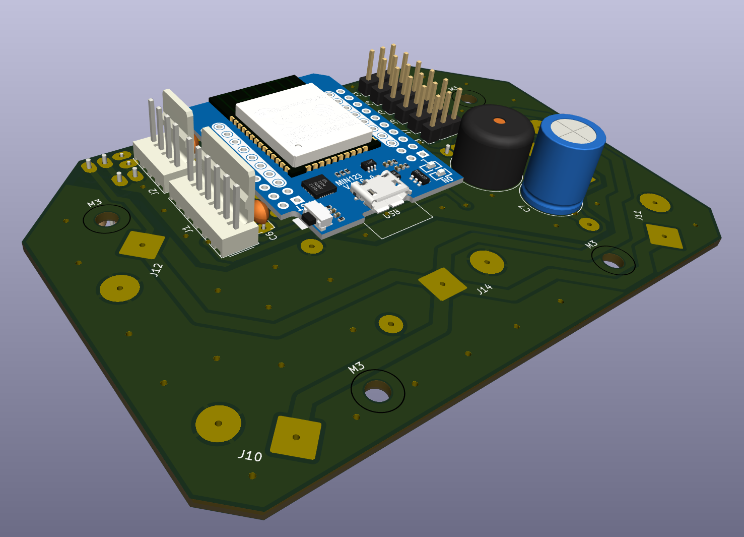
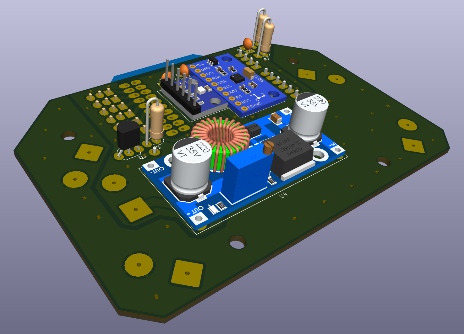
This repository contains the PCB designs and hardware documentation for a flight controller extension board based on the esp-fc project. The board is designed to connect an ESP32 microcontroller to a set of peripherals commonly used in unmanned aerial vehicles (UAVs) and robotics.
The project is intended to be developed using modular components commonly found in Arduino projects. This makes it easier for hobbyists to source and manipulate the parts, facilitating both assembly and PCB construction.
The project contains two PCB versions:
v1-single-sided: A one-layer PCB version, considered functional and stable, but not actively maintained. Note: This version has not yet been built or tested, as its dimensions are too large to fit inside the intended drone frame.
v2-double-sided: A two-layer PCB version, under active development, with continuous improvements and upgrades.
Microcontroller: ESP-WROOM-32 - ESP32 D1 Mini DevKit
IMU & Barometer: SPI connection to MPU9250 and BMP250 (separated modules)
Motor Outputs: 4 motor outputs, supporting PWM, Oneshot and DShot protocols
Serial Interfaces:
Serial1: USB-to-serial for configuration (through Betaflight Configurator)Serial2: Connection to ELRS receiver (CRSF protocol)Serial3: Optional GPS or other peripheral like vtx smart audio (still not implemented in version 0.2.1)Battery Monitoring: Voltage divider for battery voltage measurement
Status Indication: Piezo buzzer
Power Inputs: LiPo battery connector
Power Outputs:
The board is designed to be installed in a standard F450 X-frame drone, but may also be adapted to fit other drone models with minor modifications.
Below is a visual representation of the wiring and placement of components for the quadcopter configuration using the ESP32FC board:
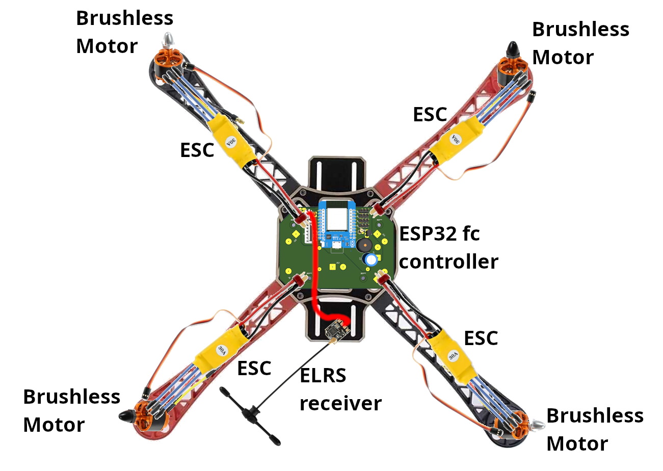
Legend:
All motor ESC signal wires are routed to the motor control pins on the PCB, while power and telemetry signals are handled via separate connections to the battery and optional modules.
hardware/                  PCB designs
  └── v1-single-sided/     Single-layer version
  └── v2-double-sided/     Dual-layer version
        └── exports/       3d images, BOM, gerber files, gcode files
        └── kicad_pcb/
  └── library/             Custom symbols & footprints
firmware/                  Optional test or support code
  └── ...
docs/                      Diagrams and usage docs and files
tools/ Scripts for BOM or Gerber generationAll initial configuration for the ESP32 module should be done following the instructions provided by @rtlopez in his esp-fc repository. This includes flashing the firmware, setting up the environment, and configuring the board.
Pin remapping specific to this board design (e.g., motor outputs, SPI, UARTs, battery monitor, buzzer) should be defined according to the layout described in the firmware/ section of this repository. Additional notes and configuration tips will be included there as development progresses.
All PCB schematics and layouts are designed using KiCad 9. Gerber files are exported using the Gerber2Order plugin for optimal manufacturing compatibility. CNC toolpaths (G-code) for PCB isolation routing are generated using FlatCAM Beta 8.994. Exports include Gerbers, BOMs, and 3D renders. Contributions are welcome, especially to the v2-double-sided version.
This project is licensed under the GPLv3, following the upstream esp-fc licensing terms.
Developed and maintained by fxrnando. Based on the work of @rtlopez.
Feel free to fork, modify, or contribute improvements to the hardware. If you build one, let us know!
| Qty | Value | Footprint | References |
|---|---|---|---|
| 6 | 100n | Capacitor_THT:C_Disc_D3.8mm_W2.6mm_P2.50mm | C1, C2, C3, C4, C5, C6 |
| 6 | Conn_01x03_Pin | Connector_PinHeader_2.54mm:PinHeader_1x03_P2.54mm_Vertical | J3, J4, J5, J6, J7, J8 |
| 6 | Screw_Terminal_01x02 | Connector_Wire:SolderWire-2.5sqmm_1x02_P8.8mm_D2.4mm_OD4.4mm | J9, J10, J11, J12, J13, J14 |
| 4 | MountingHole_3.2mm_M3 | MountingHole:MountingHole_3.2mm_M3 | M3, M3, M3, M3 |
| 1 | 1k | Resistor_THT:R_Axial_DIN0309_L9.0mm_D3.2mm_P2.54mm_Vertical | R3 |
| 1 | 22k | Resistor_THT:R_Axial_DIN0309_L9.0mm_D3.2mm_P2.54mm_Vertical | R1 |
| 1 | 2N3904 | Package_TO_SOT_THT:TO-92_Inline_Wide | Q1 |
| 1 | 3.3k | Resistor_THT:R_Axial_DIN0309_L9.0mm_D3.2mm_P2.54mm_Vertical | R2 |
| 1 | 47u | Capacitor_THT:C_Radial_D10.0mm_H12.5mm_P5.00mm | C7 |
| 1 | Buzzer | Buzzer_Beeper:Buzzer_12x9.5RM7.6 | BZ1 |
| 1 | Conn_01x04_Pin | Connector_Molex:Molex_KK-254_AE-6410-04A_1x04_P2.54mm_Vertical | J2 |
| 1 | Conn_01x06_Pin | Connector_Molex:Molex_KK-254_AE-6410-06A_1x06_P2.54mm_Vertical | J1 |
| 1 | esp32-wemos-d1-mini | esp32-wemos-d1-mini:esp32-wemos-d1-mini | U1 |
| 1 | ~ | esp32-wemos-d1-mini:mpu9250 | U2 |
| 1 | ~ | esp32-wemos-d1-mini:xl4005 DC-DC stepdown module | U4 |
| 1 | ~ | esp32-wemos-d1-mini:bmp280 | U3 |
fxrnando/esp32FC-PCB
This project is about creating a PCB board for the rtlopez esp-fc project


FrameworkComputer/ExpansionCards
Reference designs and documentation to create Expansion Cards for the Framework Laptop

mntmn/amiga2000-gfxcard
MNT VA2000, an Open Source Amiga 2/3/4000 Graphics Card (Zorro II/III), written in Verilog

hackclub/OnBoard
💡 Join 1,000 teenagers and make your first PCB with a $100 grant!


strangeparts/niubi-headphones
Flexible circuit board design for adding a headphone jack to an iPhone 7


baldengineer/bit-preserve
Project for capturing vintage, classic, aka old computer schematics in KiCad.
It measures 96.2 × 65.9 mm and has 2 copper layers, 1.6 mm thick.
34 parts. The full list of its parts is on this page, with links to each part's symbol and footprint where PCBKit's library has them.
From the fxrnando/esp32FC-PCB repository on GitHub, at the commit this page was made from: the board is hardware/v2-double-sided/kicad_pcb/esp32FC.kicad_pcb and its schematic hardware/v1-single-sided/kicad_pcb/esp32FC.kicad_sch. PCBKit opens the board in the browser, with nothing to install.
Its repository publishes it under the GPL-3.0 licence: you may reuse it on that licence's terms (keep the author's notice, and for a copyleft licence share your changes alike).