2 layers50 × 23.2 mm
Analog
hoglet67/RGBtoHDMI
Bare-metal Raspberry Pi project that provides pixel-perfect sampling of Retro Computer RGB/YUV video and conversion to HDMI
32 parts1kGPL-3.0

 frederiekberthier/RPI_test
Test library om RPI hardwarematig te testen
Gpio adapter is an open-source printed circuit board by frederiekberthier, from the frederiekberthier/RPI_test repository on GitHub, published under the CC0-1.0 licence. It is a 2-layer board of 70 × 60.8 mm with 32 parts on 53 nets, routed with 102 tracks and 0 vias.
Its parts include 26 resistors and 2 connectors. It belongs with the interfaces and adapters boards of this library.
Test library om RPI hardwarematig te testen
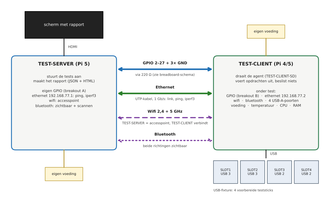
Namen: de twee Pi's heten TEST-SERVER en TEST-CLIENT. Aan de scripts geef je server of client mee
(./install.sh server); de hostnamen worden test-server en test-client. De namen gaan over de Pi's, niet over het
netwerkprotocol: de agent op de TEST-CLIENT is technisch een HTTP-server en de TEST-SERVER roept hem aan.
"Raspberry Pi tester" is de naam van de applicatie.
Eén script (install.sh) doet alles: voorcontrole, pakketten (apt), software, hostnaam, vrije GPIO-pinnen, wifi-land,
scherm met kiosk (TEST-SERVER), dienst en het vaste IP-adres. Het controleert per onderdeel eerst of het er al staat, dus je
kunt het veilig opnieuw uitvoeren. De stappen zijn voor de TEST-SERVER en de TEST-CLIENT-SD hetzelfde; alleen server of client verschilt.
BE) en SSH in.sudo apt install -y git
git clone https://github.com/frederiekberthier/RPI_test.git
cd RPI_testsudo ./install.sh server --check # of: clientsudo ./install.sh server # of: clientsudo rebootsudo ./image/verify.sh server (of client)sudo ./image/diagnose.sh verzamelt alle relevante uitvoer in één bestand om te delen.| Optie | Wat het doet |
|---|---|
--check | toont per onderdeel aanwezig, ontbreekt of onbekend; wijzigt niets |
--force | past alles opnieuw toe, ook wat al aanwezig lijkt |
--readonly | (alleen client) maakt het bestandssysteem alleen-lezen na de installatie |
--skip-preflight | slaat de voorcontrole over |
Bijwerken naar een nieuwe versie: git pull && sudo ./install.sh server. Het script ziet dat alleen de software
verouderd is, vervangt die en herstart de dienst; de rest wordt overgeslagen.
Meer: docs/eerste-installatie.md (draaiboek voor de eerste keer, met controlelijst), docs/image.md (scherm, diensten, SD klonen, probleemoplossing) en docs/opstelling.md (onderdelen en bedrading van het breadboard).
pip install -e .[dev]
python -m pytest
python -m rpitest --mock                                   # gezonde gesimuleerde Pi
python -m rpitest.ui --mock                                # het scherm van de TEST-SERVER, op http://127.0.0.1:8080
python -m rpitest --mock --fault stuck_low:C:5 --fault bridge:C:10:11 --fault open:7
python -m rpitest --mock --fault eth_100 --fault wifi_5g_dead --fault bt_client_tx_dead
Faalspecificaties: stuck_low|stuck_high:<S|C>:<pin>, bridge:<S|C>:<a>:<b>, open:<pin>.
Systeemfouten: eth_100, eth_errors, eth_slow, eth_loss, no_wifi, wifi_5g_dead, wifi_weak,
no_bt, bt_client_rx_dead, bt_client_tx_dead, server_no_wifi, server_no_bt,
usb_slotN_dead|usb2|corrupt|slow (N = 1..4), usb_no_sticks, usb_overcurrent, usb_disconnect,
power_undervolt, power_undervolt_history, power_hot, power_warm, power_throttle, power_cpu_error,
power_ram_error, power_core_missing, power_no_sensor, power_dip, power_throttle_blip.
Klaar: skelet, agent (JSON-RPC over HTTP), mock met foutinjectie, GPIO-checks, JSON/HTML-rapport,
echte GPIO-backend (libgpiod 2.x, enkel getest met een nep-gpiod), bedradingshandleiding,
netwerk-, wifi-, bluetooth-, USB- en voeding/temperatuurchecks (alleen getest met simulatie en nagebootste tooluitvoer).
Scherm met startknop en live resultaten (rpitest.ui), en één installatiescript voor server en TEST-CLIENT (install.sh),
getest tegen nagebootste systeemopdrachten.
Nog te doen: alles op echte Pi's bevestigen (ook het installatiescript).
| Qty | Value | Footprint | References |
|---|---|---|---|
| 26 | 220 | R_Axial_DIN0207_L6.3mm_D2.5mm_P7.62mm | R2, R10, R11, R12, R13, R14, R15, R16, R17, R18, R19, R20, R21, R22, R23, R24 +10 |
| 4 | M3 | MountingHole_3.2mm_M3 | H1, H2, H3, H4 |
| 2 | 2x20 | IDC-Header_2x20_P2.54mm_Horizontal_Mirrored | J1, J2 |
hoglet67/RGBtoHDMI
Bare-metal Raspberry Pi project that provides pixel-perfect sampling of Retro Computer RGB/YUV video and conversion to HDMI

hackclub/OnBoard
💡 Join 1,000 teenagers and make your first PCB with a $100 grant!


octosavvi/ESPKey
Wiegand data logger, replay device and micro door-controller

zmaker/arduino_cookbook
gli sketch del nuovo progetto Arduino Cookbook e dei video di YouTube

murexrobotics/electrical
Highly integrated electronics design and printed circuit boards (PCBs) for the MATE ROV Competition. Attempt the impossible.

swharden/AVR-projects
A collection of standalone AVR projects written in C

hardenedlinux/cheap-pcb
Cheap PCB: Better understanding the current status of hardware supply chain
It measures 70 × 60.8 mm and has 2 copper layers, 1.6 mm thick.
32 parts. The full list of its parts is on this page, with links to each part's symbol and footprint where PCBKit's library has them.
From the frederiekberthier/RPI_test repository on GitHub, at the commit this page was made from: the board is hardware/gpio-adapter/kicad/gpio-adapter.kicad_pcb. PCBKit opens the board in the browser, with nothing to install.
Its repository publishes it under the CC0-1.0 licence: you may reuse it on that licence's terms (keep the author's notice, and for a copyleft licence share your changes alike).