
2 layers60.5 × 76.5 mm
 frc4904/CANController
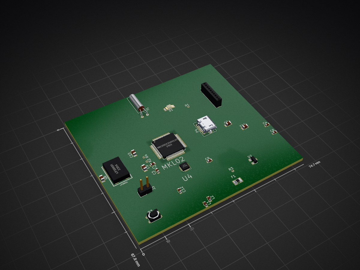
ROBOTCircuitBoard is an open-source printed circuit board by frc4904, from the frc4904/CANController repository on GitHub. It is a 2-layer board with 28 parts on 77 nets.
It is built around the MK20DX256VLH7. Its parts include 11 capacitors, 4 resistors, 4 connectors, 3 ICs and 2 diodes. It belongs with the NXP (LPC, Kinetis, i.MX RT) boards of this library.
This is a KiCAD file for a PCB that converts the serial bus data from sensors to CAN bus data using an intermediary embedded Teensy 3.2 which are then passed through DB15 connectors and VGA cables to other similar PCBs (other board schematics can be found in different repositories on github.com/roboticsteam4904). The main sensors are LiDAR and encoders but it can be used with most sensors that have more than 5-pin connections. It also functions as power and data signal for LED strips scuh as the Adafruit Neopixels.
| Qty | Value | Footprint | References |
|---|---|---|---|
| 4 | 2.2uF | Capacitors_SMD:C_0805 | C2, C5, C10, C11 |
| 3 | 0.1uF | Capacitors_SMD:C_0603 | C4, C6, C8 |
| 3 | CP 0.1uF | Capacitors_SMD:C_0603 | C3, C7, C12 |
| 2 | 33 | Resistors_SMD:R_0201 | R3, R4 |
| 2 | 470 | Resistors_SMD:R_0201 | R1, R2 |
| 2 | L Ferrite | Capacitors_SMD:C_0603 | L1, L2 |
| 1 | Analog 9-0 | Socket_Strips:Socket_Strip_Straight_1x10_Pitch1.27mm | J1 |
| 1 | CONN_01X02 | Pin_Headers:Pin_Header_Straight_1x02_Pitch2.54mm | J3 |
| 1 | CP 2.2uF | Capacitors_SMD:C_0805 | C9 |
| 1 | Crystal 16MHz | Crystals:Crystal_AT310_d3.0mm_l10.0mm_Horizontal | Y1 |
| 1 | D_Schottky_AAK | Diodes_SMD:D_SOT-23_ANK | D2 |
| 1 | Fuse | Fuse_Holders_and_Fuses:Fuse_SMD1206_Reflow | F1 |
| 1 | LED | LEDs:LED_1206 | D1 |
| 1 | LP38691 | kicadfootprints:lp38691 | U3 |
| 1 | MK20DX256VLH7 | MK20DX256VLH7:QFP50P1200X1200X160-64N | U2 |
| 1 | MKL02 | Teensy_DIY_v1.0:Teensy_DIY_v1.0-QFN50P300X300X100-17N | U4 |
| 1 | Pushbutton NO | Buttons_Switches_SMD:SW_SPST_PTS810 | P3 |
| 1 | USB_OTG | Connectors:USB_Micro-B | P4 |

Project-Aurora/Project-Aurora
An Attempt at making an Open Source Fully RGB Backlit 60% Keyboard


jenschr/Teensy3.2-example
A verified example PCB based on the Teensy 3.2 schematics


28 parts, built around the MK20DX256VLH7. The full list of its parts is on this page, with links to each part's symbol and footprint where PCBKit's library has them.
From the frc4904/CANController repository on GitHub, at the commit this page was made from: the board is ROBOTCircuitBoard.kicad_pcb. PCBKit opens the board in the browser, with nothing to install.
Its repository states no licence, so its author keeps all rights: ask frc4904 before reusing the design.