
2 layers
Encoder
byrantech/laptop
anyon_e, a highly integrated, high end, open source laptop. Attempt the impossible.
7 parts4.3kMIT

 foriequal0/shutter-timing-tool
Shutter timing tool for Canon AE-1
Shutter timing tool is an open-source printed circuit board by foriequal0, from the foriequal0/shutter-timing-tool repository on GitHub. It is a 2-layer board of 60 × 24 mm with 7 parts on 5 nets, routed with 43 tracks and 3 vias.
It is built around the VEMD4200FX01. Its parts include 3 resistors, 3 diodes and 1 connector.
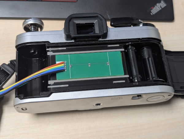
This repository contains source code and schematics for the shutter timing tool. It is designed to measure following timings of Canon AE-1:
VEMD4200FX01 photodiodes (x3)platformio run -t upload -e picoPCB sensor's pins shoud be connected to the RPI Pico's ADC0, ADC1, ADC2.
(ADC0 is for the rightmost sensor when you see it from the back of the camera,
and ADC2 is for the leftmost one)
UART0 RX pinUART0 RX pin is used to report the timing.
Connect it to your PC through USB to UART module.
I've used platformio device monitor --baud 115200
Align the board so that all three sensors are exposed when the shutter is opened.
Remove the lens, and place a light source in front of the camera. The light source should be bright and uniform.
Output from UART0 RX should look like this:
exposure: 170.0 ms, opening: 12312 us, closing: 11231 us
exposure: 83.1 ms, opening: 12312 us, closing: 11231 usADC1 (middle sensor).ADC0 is exposed and the time ADC2 is exposed.ADC0 is no longer exposed and the time ADC2 is no longer exposed.| Qty | Value | Footprint | References |
|---|---|---|---|
| 3 | 510k | Resistor_SMD:R_0805_2012Metric | R1, R2, R3 |
| 3 | VEMD4200FX01 | Library:VEMD4200FX01 | D4, D5, D6 |
| 1 | Conn_01x05_Socket | Connector_PinSocket_2.54mm:PinSocket_1x05_P2.54mm_Vertical | J2 |
byrantech/laptop
anyon_e, a highly integrated, high end, open source laptop. Attempt the impossible.


AxxAxx/AxxSolder
STM32 Based soldering station for JBC cartridges, 9-24 VDC and USB-PD power


jamro/tiny-engineer
A small desktop robot that brings an AI coding assistant to life, physically acting out when it reads files, thinks, writes code, and finishes work.

hoglet67/RGBtoHDMI
Bare-metal Raspberry Pi project that provides pixel-perfect sampling of Retro Computer RGB/YUV video and conversion to HDMI

It measures 60 × 24 mm and has 2 copper layers, 1.6 mm thick.
7 parts, built around the VEMD4200FX01. The full list of its parts is on this page, with links to each part's symbol and footprint where PCBKit's library has them.
From the foriequal0/shutter-timing-tool repository on GitHub, at the commit this page was made from: the board is pcb/pcb.kicad_pcb and its schematic pcb/pcb.kicad_sch. PCBKit opens the board in the browser, with nothing to install.
Its repository states no licence, so its author keeps all rights: ask foriequal0 before reusing the design.