2 layers134.9 × 48.5 mm

 flaviut/30a-water-heater-controller2
Makes any resistive water heater 30A or less WiFi controllable
Wifi-30A relay is an open-source printed circuit board by flaviut, from the flaviut/30a-water-heater-controller repository on GitHub, published under the CERN-OHL-S-2.0 licence. It is a 2-layer board of 85 × 56 mm with 42 parts on 37 nets, routed with 232 tracks and 92 vias.
It is built around the ESP-WROOM-02, IRM-05-12 and ADS1115IDGS, with the TPS54331DR-JSM, J115F21C12VDCS.9 and SS54 among its other parts. Its parts include 14 resistors, 13 capacitors, 3 ICs, 3 diodes and 3 switches. It belongs with the radio and wireless and home automation and IoT boards of this library.


This board contains a design for a water heater controller that is good for up to 30A water heaters.
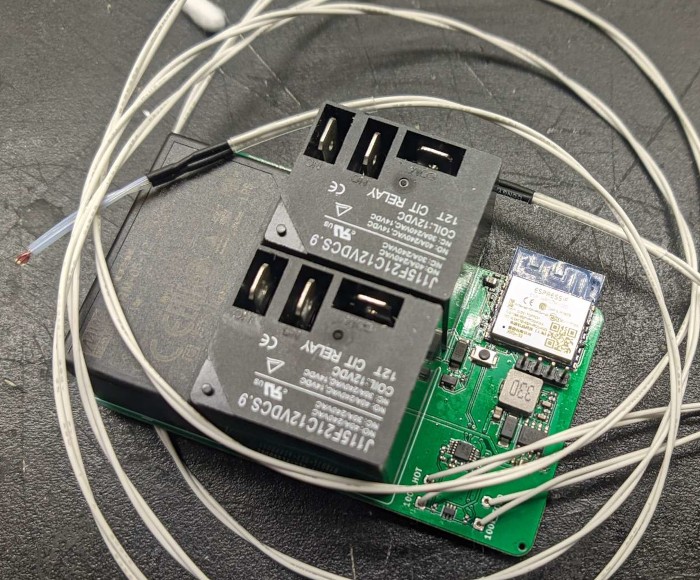
Working with high currents and mains voltages is dangerous. Death from electrical shock & house fires are both real risks with this project.
This project comes with no warranty, and is not examined by or listed by any NRTL. You are solely responsible for determining if it is safe.
The latest release contains all the files you need to have this PCB manufactured & 90% assembled by a vendor of your choice. I used JLCPCB.
The defaults are fine. You may wish to ask them to not assemble the thermistor connectors to save a couple bucks.
esphome.yaml as a template100k_HOT, and feed it out of the enclosure
| Qty | Value | Footprint | References |
|---|---|---|---|
| 7 | 100n | Capacitor_SMD:C_0402_1005Metric | C5, C7, C8, C10, C11, C12, C13 |
| 7 | 10k | Resistor_SMD:R_0402_1005Metric | R2, R3, R8, R9, R12, R13, R14 |
| 4 | 100k | Resistor_SMD:R_0402_1005Metric | R6, R7, R10, R11 |
| 3 | 22u | Capacitor_SMD:C_0805_2012Metric | C1, C3, C9 |
| 2 | J115F21C12VDCS.9 | wifi-30A-relay:Relay_SPDT_CIT-J115F2 | K1, K2 |
| 2 | SS54 | Diode_SMD:D_SMA | D1, D2 |
| 1 | 100k_COLD | Connector_JST:JST_XH_B2B-XH-AM_1x02_P2.50mm_Vertical | 100k_COLD |
| 1 | 100k_HOT | Connector_JST:JST_XH_B2B-XH-AM_1x02_P2.50mm_Vertical | 100k_HOT |
| 1 | 15n | Capacitor_SMD:C_0603_1608Metric | C6 |
| 1 | 1k | Resistor_SMD:R_0402_1005Metric | R1 |
| 1 | 2.4k | Resistor_SMD:R_0402_1005Metric | R5 |
| 1 | 3.3n | Capacitor_SMD:C_0603_1608Metric | C4 |
| 1 | 33u | Inductor_SMD:L_TDK_SLF6028 | L1 |
| 1 | 7.5k | Resistor_SMD:R_0402_1005Metric | R4 |
| 1 | 8.2n | Capacitor_SMD:C_0603_1608Metric | C2 |
| 1 | ADS1115IDGS | Package_SO:TSSOP-10_3x3mm_P0.5mm | U3 |
| 1 | AO3400A | Package_TO_SOT_SMD:SOT-23 | Q1 |
| 1 | ESP-WROOM-02 | RF_Module:ESP-WROOM-02 | U1 |
| 1 | IRM-05-12 | Converter_ACDC:Converter_ACDC_MeanWell_IRM-05-xx_THT | PS1 |
| 1 | PROG | Connector_PinHeader_2.54mm:PinHeader_1x04_P2.54mm_Vertical | J1 |
| 1 | SKRKAEE020 | Button_Switch_SMD:SW_Push_SPST_NO_Alps_SKRK | SW1 |
| 1 | SMF05CT1G | Package_TO_SOT_SMD:SOT-363_SC-70-6 | D3 |
| 1 | TPS54331DR | Package_SO:SOIC-8_3.9x4.9mm_P1.27mm | U2 |

Fluepke/Fluepdot
Project for controlling Annax flipdot panels used by the Berliner Verkehrsbetriebe

speters/CNC_BoosterWing
CNC breakout board for the TM4C1294CL Launchpad running grbHAL

Camperlux/vancontroller
VanController: ESP32-S3 12 V campervan controller board (6 fused relays, 6 PWM dimmers, CAN, RS485, GPS) - KiCad 10 design, manufacturing files and enclosure. Free for non-commercial use.

npgo22/Serie
The board itself is based around an STM32H723, the fastest microcontroller supported by Klipper at the moment.


Marimugeshbabu/STM32-Industrial-Data-Logger
4-layer STM32 Industrial Data Logger designed in KiCad 9 with RS485, microSD, voltage/current sensing and protection circuitry.
It measures 85 × 56 mm and has 2 copper layers, 1.6 mm thick.
42 parts, built around the ESP-WROOM-02, IRM-05-12, ADS1115IDGS and TPS54331DR-JSM. The full list of its parts is on this page, with links to each part's symbol and footprint where PCBKit's library has them.
From the flaviut/30a-water-heater-controller repository on GitHub, at the commit this page was made from: the board is wifi-30A-relay.kicad_pcb and its schematic wifi-30A-relay.kicad_sch. PCBKit opens the board in the browser, with nothing to install.
Its repository publishes it under the CERN-OHL-S-2.0 licence: you may reuse it on that licence's terms (keep the author's notice, and for a copyleft licence share your changes alike).