
2 layers75 × 106.5 mm

 flaviut/5v-inverting-buck
Design for an inverting 5V buck-boost regulator based on the MT2499A, with performance data
Inverting buck boost is an open-source printed circuit board by flaviut, from the flaviut/5v-inverting-buck repository on GitHub. It is a 2-layer board of 15 × 18 mm with 12 parts on 8 nets, routed with 41 tracks and 31 vias.
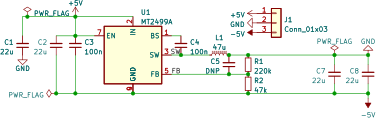
It is built around the MT2499A. Its parts include 7 capacitors, 2 resistors, 1 IC, 1 connector and 1 inductor. It belongs with the power boards of this library.
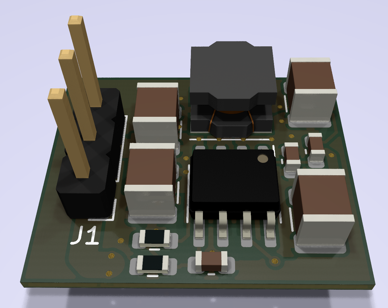
Using the documentation in TI's SLVA458B, "Creating an Inverting Power Supply Using a Synchronous Step-Down Regulator", I've designed an inverting buck-boost regulator using the super-cheap Aerosemi MT2499A, and characterized its performance somewhat.
There's a massive amount of 7kHz ripple, up to 500mV before stopping testing at 300mA.
This seems to be related to very poor regulator stability. Placing 33pF in C5 improves ripple to 30mV between 0-220mA out, but the ripple is back to 500mV at 230mA.
| Cff | Imax |
|---|---|
| 32pF | 225mA |
| 54pF | 285mA |
Linear interpolation indicates 133pF would be needed for stability at 500mA, but I'm not sure if linear interpolation is valid here.
I also suspect that it is not possible to create a perfectly compensated regulator here, since the MT2499A is internally compensated, and the procedure that SLVA458B describes to compensate the regulator is just not possible.
| Qty | Value | Footprint | References |
|---|---|---|---|
| 4 | 22u | Capacitor_SMD:C_1210_3225Metric | C1, C2, C7, C8 |
| 2 | 100n | Capacitor_SMD:C_0603_1608Metric | C3, C4 |
| 1 | 200k | Resistor_SMD:R_0603_1608Metric | R1 |
| 1 | 47k | Resistor_SMD:R_0603_1608Metric | R2 |
| 1 | 47u | Inductor_SMD:L_Taiyo-Yuden_NR-50xx | L1 |
| 1 | Conn_01x03 | Connector_PinHeader_2.54mm:PinHeader_1x03_P2.54mm_Vertical | J1 |
| 1 | DNP | Capacitor_SMD:C_0603_1608Metric | C5 |
| 1 | MT2499A | Package_SO:SOIC-8-1EP_3.9x4.9mm_P1.27mm_EP2.62x3.51mm_ThermalVias | U1 |
It measures 15 × 18 mm and has 2 copper layers, 0.57 mm thick.
12 parts, built around the MT2499A. The full list of its parts is on this page, with links to each part's symbol and footprint where PCBKit's library has them.
From the flaviut/5v-inverting-buck repository on GitHub, at the commit this page was made from: the board is inverting-buck-boost.kicad_pcb and its schematic inverting-buck-boost.kicad_sch. PCBKit opens the board in the browser, with nothing to install.
Its repository states no licence, so its author keeps all rights: ask flaviut before reusing the design.

Open-Source-Model-Railway-Electronics/OS-Servo-Decoder
The OS-Servo-Decoder is a simple and robust DCC accessory decoder designed for driving up to 8 servo motors. It supports modern model railroads with flexible configuration options, external relay modules for polarity…


github-linguist/linguist
Language Savant. If your repository's language is being reported incorrectly, send us a pull request!


google/mozc-devices
Circuit diagrams and firmware source code for Gboard DIY keyboards

