
2 layers45 × 72 mm
Relay
adarwoo/modbus_relay
A modbus RTU relay board with 3 relays for the CNC. This uses the ASX framework
43 parts1
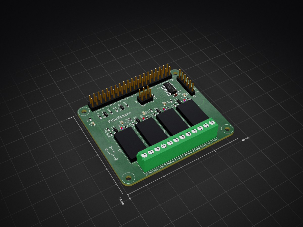
 FibStack/pi-switcher-plus
The FibStack PiSwitcher Plus board was designed to help you in your next automation project.
Piswitcher plus board is an open-source printed circuit board by FibStack, from the FibStack/pi-switcher-plus repository on GitHub. It is a 2-layer board of 65 × 56 mm with 48 parts on 72 nets, routed with 348 tracks and 12 vias.
It is built around the ATTINY824-SSU. Its parts include 18 resistors, 9 diodes, 6 transistors, 4 connectors and 1 capacitor. It belongs with the AVR (ATmega, ATtiny) boards of this library.
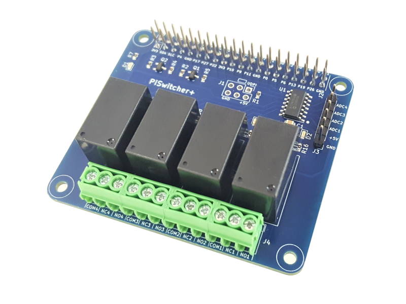
The FibStack PiSwitcher Plus board was designed to help you in your next automation project.
The board has four high-quality relays allowing it to switch high voltage and currents. Controlling a steam iron or an oven is not the right task for the board, but it will handle most home appliances below 1200W. Each relay has an LED indicator showing when the NO (Normal Open) contact is connected to the COM (Common).
Additionally, the board has four 12-bit ADC channels that can convert electric signals up to 5 volts. The converted value allows more flexibility in the automation decision logic.
The FibStack Dashboard allows testing things on the fly without writing any code. Alternatively, you can control the board using the CLI tool or programmatically using provided libraries. See the Documentation section below for links to Getting Started guide and references.
WARNING. Hazard of severe electrical shock or burn when using High Voltage/Current applications. Obey High Voltage/Current safety procedures. FibStack is not responsible for any damage or injury that occurs from improper High Voltage use.
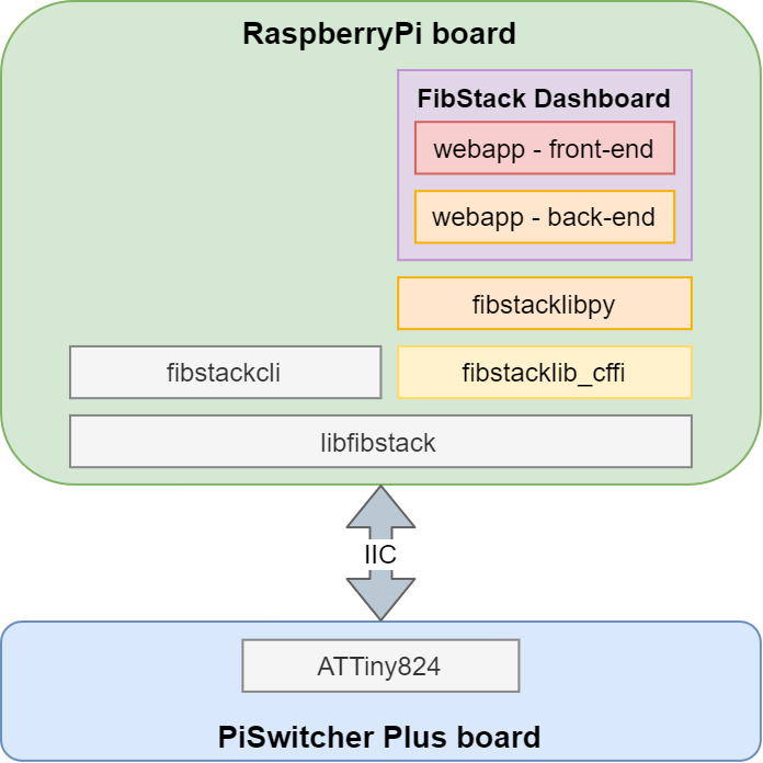
On the PiSwitcher Plus board, the ATTiny824 microcontroller receives commands from the RaspberryPi board through the I2C interface. The software package facilitates communication between the Raspberry Pi and the PiSwitcher Plus board.
The libfibstack library is used by any library or tool directly or indirectly.
You can use the libfistack library directly in your C project. Please consult the C API Reference.
The fibstackcli is a convenient tool to get device statuses and switch relays from the command lines.
The fibstacklib_cffi is a Python wrapper around the libfistack library. We provide a fibstacklibpy library for convenience if you want to use it in your Python projects. See the Python API Reference.
The FibStack Dashboard is a convenient web-based UI tool that allows you to control the PiSwitcher Plus board. It consists of the back-end python script and a front-end project that uses Angular.
libfibstack library wrapper for Python.fibstacklib_cffi project.| # | Components | Recommended models | Footprint | Quantity |
|---|---|---|---|---|
| 1 | PCB | Recommended two-layer PCB board of 1.6 mm thickness | 1 | |
| 2 | U1 | ATTiny824-SSU | SOIC-14 package, 3.9x8.7mm pitch: 1.27mm | 1 |
| 3 | C1 | Any 100nF 50V SMD capacitor | 0805 (2012 metric) | 1 |
| 4 | Q1 - Q6 | 2N7002 N-channel MOSFET transistor, 60V 300mA | SOT-23-2 | 6 |
| 5 | RL1 - RL4 | General purpose SPDT 5VDC relay. Recommended models J0971C, YX201-S-105D, or similar. | J0971C | 4 |
| 6 | D1 | SMD LED RED | 0603 (1608 metric) | 1 |
| 7 | D2, D3, D6, D7 | SMD LED GREEN | 0603 (1608 metric) | 4 |
| 8 | D4, D5, D8, D9 | Any general purpose SMD Diode, 75V, 200mA | MicroMELF | 4 |
| 9 | R1, R2, R3, R4, R5, R9, R10, R15, R16 | Any 10K 5% 1/4W SMD Resistor | 0603 (1608 metric) | 9 |
| 10 | R6, R7, R8, R11, R12, R13, R14, R17, R18 | Any 1K 5% 1/4W SMD Resistor | 0603 (1608 metric) | 9 |
| 11 | J1 | Extended GPIO Male Female Header, 2x20, pitch 2.54mm | 2x20 - P2.54mm | 1 |
| 12 | J2 | Optional, Male Header Connector, 2x3, pitch 2.54mm | 2x3 - P2.54mm | 1 |
| 13 | J3 | Male Header Connector, 1x6, pitch 2.54mm | 1x6 - P2.54mm | 1 |
| 14 | J4 | Screw Terminal Block 1x12, Pitch 3.5mm. Alternatively, you can use two of 1x6, three of 1x4, or four of 1x3. | 1x12 - P3.5mm | 1 |
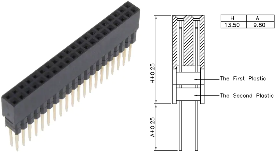
For the Extended GPIO Male Female header connector (J1), we recommend using a component as shown in the figure below. The female part has a height of 8.5mm plus two plastic pieces of 2.5mm. The female part is placed on the bottom of the board and soldered on the top of the board. The male pins should be 9.8mm or longer to allow an additional expansion board to be connected.
The software package communicates with PiSwitcher Plus through the I2C (or IIC, TWI) interface. Theoretically, you can send the instructions from any device that supports the I2C interface. We developed a simple protocol that uses only five commands for now. You can write your software to control the board using the commands below.
| # | Command | Description |
|---|---|---|
| 1 | version | Returns a constant string from the board that represents the Firmware/Hardware version. |
| 2 | setaddr:<new_address_value> | Set the PiSwitcher Plus board I2C address. The valid address value should be an integer between 3 and 119. |
| 3 | status | Returns a set of values delimited by a colon :. Each value represents a device value. The first four values represent the Relay values, 1 means the relay's coil is energized, 0 otherwise. The last four values represent the values from ADC channels. Example: 0:1:1:0:120:1023:0:785. |
| 4 | get:<device_id> | Returns the value (status) for the specified device. The relay devices IDs are from 0 to 3 inclusive. The ADC channel device IDs are from 4 to 7 inclusive. |
| 5 | set:<device_id>:<value> | Sets the value for the specified device. This command is used to switch relay devices on the PiSwitcher Plus board. The set command doesn't work for ADC devices as they are Read-Only. The valid values for the device_id are from 0 to 3 inclusive. The possible values are 0 and 1. |
This product is open source!
Please review the LICENSE.md file for license information. Distributed as-is; no warranty is given.
| Qty | Value | Footprint | References |
|---|---|---|---|
| 9 | 10K | Resistor_SMD:R_0603_1608Metric | R1, R2, R3, R4, R5, R9, R10, R15, R16 |
| 9 | 1K | Resistor_SMD:R_0603_1608Metric | R6, R7, R8, R11, R12, R13, R14, R17, R18 |
| 6 | 2N7002 | fibstack_piswitcher_plus_lib:SOT-23-3 | Q1, Q2, Q3, Q4, Q5, Q6 |
| 5 | LED | LED_SMD:LED_0603_1608Metric | D1, D2, D3, D6, D7 |
| 4 | D | Diode_SMD:D_MicroMELF | D4, D5, D8, D9 |
| 4 | J0971C | fibstack_piswitcher_plus_lib:J0971C | RL1, RL2, RL3, RL4 |
| 4 | MountingHole | fibstack_piswitcher_plus_lib:CustomMountingHole | H1, H2, H3, H4 |
| 1 | 100n | Capacitor_SMD:C_0805_2012Metric | C1 |
| 1 | ATtiny824-SS | Package_SO:SOIC-14_3.9x8.7mm_P1.27mm | U1 |
| 1 | Conn_01x06_Male | Connector_PinHeader_2.54mm:PinHeader_1x06_P2.54mm_Vertical | J3 |
| 1 | Conn_02x03_Odd_Even | Connector_PinHeader_2.54mm:PinHeader_2x03_P2.54mm_Vertical | J2 |
| 1 | LOGO | fibstack_piswitcher_plus_lib:fibstack_logo | G*** |
| 1 | Raspberry_Pi_2_3 | Connector_PinHeader_2.54mm:PinHeader_2x20_P2.54mm_Vertical | J1 |
| 1 | Screw_Terminal_01x12 | TerminalBlock_4Ucon:TerminalBlock_4Ucon_1x12_P3.50mm_Horizontal | J4 |
It measures 65 × 56 mm and has 2 copper layers, 1.6 mm thick.
48 parts, built around the ATTINY824-SSU. The full list of its parts is on this page, with links to each part's symbol and footprint where PCBKit's library has them.
From the FibStack/pi-switcher-plus repository on GitHub, at the commit this page was made from: the board is piswitcher_plus_board/piswitcher_plus_board.kicad_pcb and its schematic piswitcher_plus_board/piswitcher_plus_board.kicad_sch. PCBKit opens the board in the browser, with nothing to install.
Its repository states no licence, so its author keeps all rights: ask FibStack before reusing the design.
adarwoo/modbus_relay
A modbus RTU relay board with 3 relays for the CNC. This uses the ASX framework


hackclub/OnBoard
💡 Join 1,000 teenagers and make your first PCB with a $100 grant!

adamws/kicad-kbplacer
KiCad plugin for automatic keyboard's key placement and routing


softerhardware/Hermes-Lite2
A second generation low-cost amateur HF software defined radio transceiver.

CRImier/MyKiCad
My KiCad boards. Can't be bothered uploading individually anymore, so here you go.