

2 layers102.1 × 119.4 mm
 ffosilva/psu-controller
Discrete ACPI-coordinated ATX power supply controller with remote ESP wake and telemetry latching
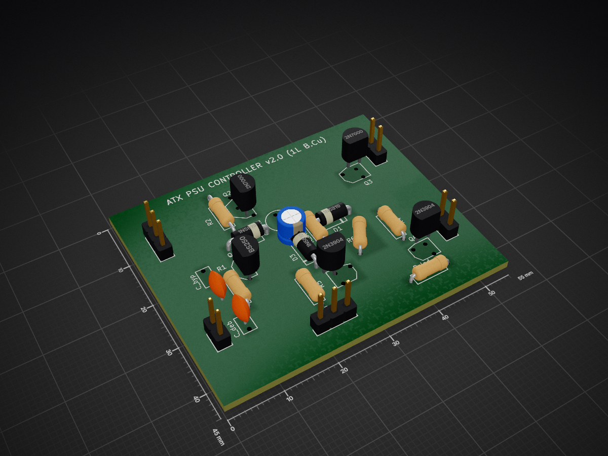
Atx psu controller is an open-source printed circuit board by ffosilva, from the ffosilva/psu-controller repository on GitHub, published under the MIT licence. It is a 2-layer board of 55 × 45 mm with 23 parts on 15 nets, routed with 60 tracks and 0 vias.
It is built around the BS250. Its parts include 5 resistors, 5 transistors, 5 connectors and 3 diodes. It belongs with the power and computers and single-board computers boards of this library.
psu-controller)


A discrete, analog hardware controller designed to sequence and manage standard ATX power supplies for non-standard motherboards, repurposed compute platforms (such as the AMD BC-250 mining board), single-board computers, and custom electronics fixtures.
Repurposed compute hardware (such as headless crypto-mining boards like the AMD BC-250, embedded industrial boards, and retro computing conversions) often lack standard front-panel ATX power management circuits.
Without a dedicated controller:
PS_ON# wire (green) to Ground (black) with a jumper clip or switch.The ATX Power Supply Controller eliminates jumpers by providing an intelligent, fully autonomous, discrete hardware sequency bridge between any ATX power supply, the host motherboard, and your chassis buttons/LEDs.
PS_ON# for ~3.5 seconds to allow the host to spin up.HOST_ON). Once booted, host voltage locks PS_ON# low indefinitely.BTN_OUT) through an open-drain N-channel MOSFET (2N7000), allowing:
HOST_ON drops to 0V. The controller de-asserts PS_ON# within 300 ms, putting the ATX power supply back into standby ($< 50\ \mu\text{A}$ quiescent draw).ESP_WAKE): Accepts a 3.3V logic pulse from an ESP32, ESP8266, or Raspberry Pi Pico to power on the system remotely over WiFi/Bluetooth.ESP_WAKE directly to ground whenever the system is running, preventing accidental resets or wake loops.B.Cu only, zero vias, zero top-side copper traces) designed specifically for home etching (toner transfer / photoresist) or desktop CNC milling.+---------------------+ +-----------------------+
| Chassis Front | | ATX Power Supply |
| Panel | | (24-Pin Main) |
| | | |
| [Power Button] | | Pin 9 (+5VSB, Purp) |
| [Power LED Ring] | | Pin 16 (PS_ON#, Grn) |
| | | Pin 3 (GND, Blk) |
+----------+----------+ +-----------+-----------+
| |
| 4 wires | 3 wires
v v
+-----+--------------------------------------+-----+
| |
| ATX POWER SUPPLY CONTROLLER PCB |
| (55 mm x 45 mm Single-Sided) |
| |
+-----+--------------------------------------+-----+
^ ^
| 2-3 wires | 2 wires
| |
+----------+----------+ +-----------+-----------+
| ESP32 / ESP8266 | | Host Motherboard |
| Microcontroller | | (AMD BC-250) |
| | | |========================================================================================
CIRCUIT SCHEMATIC OVERVIEW
========================================================================================
+5VSB (J1 Pin 1, ATX Pin 9)
|
+----------------------+-------------------------------+
| | |
[R1: 10k] Source [Q1: BS250] [R_led: 330R]
| (P-Ch MOSFET) |
BTN_IN -------+------------------+ Gate v Anode
(J3 Pin 1) | | Drain [Power LED]
[C_deb: 100nF] [D2: 1N5819] (J4 Pin 1)
| | | Cathode
GND ----------+ v (J4 Pin 2)
Node [V_GATE] |
HOST_ON (3.3V TPM) -----[D1: 1N5819]-+ |
(J2 Pin 1) | |
| |
ESP_WAKE (3.3V) ----[R5: 1k]---------+-----[D3: 1N5819]--+ |
(J5 Pin 2) | | |
Collector v |
| +-------------+ |
HOST_ON ---[R6: 10k]+ Base [Q5: 2N3904] | [C_hold] | |+5VSB is active. Node V_GATE is 0V, $Q_2$ is OFF, PS_ON# floats at 5V, power draw is $< 50\ \mu\text{A}$.PS_ON# to GND.HOST_ON. Diode $D_1$ conducts, locking V_GATE to ~3.05V indefinitely.BTN_OUT) to ground. The OS registers the ACPI event and initiates a clean shutdown. PS_ON# stays grounded by HOST_ON during shutdown.HOST_ON drops to 0V. $D_1$ stops conducting, $C_{hold}$ discharges in ~300 ms, $Q_2$ turns off, and the ATX supply turns off main rails.BTN_OUT low, triggering the motherboard hardware supervisor force-off.ESP_WAKE charges $C_{hold}$ via $D_3$, turning on the PSU. When the host is already running, $Q_5$ clamps the wake input directly to GND, preventing unexpected glitches.| Header | Pin | Signal | Target Connection | Description |
|---|---|---|---|---|
| J1: ATX PSU | 1 | +5VSB | ATX 24-Pin Pin 9 (Purple) | Standby +5V DC power |
| 2 | PS_ON# | ATX 24-Pin Pin 16 (Green) | Active-low main rail enable | |
| 3 | GND | ATX 24-Pin Pin 3/5/7/15/17 (Black) | Common system ground return | |
| J2: Host Board | 1 | HOST_ON | Motherboard TPM Header Pin 1 (3.3V) | Active power telemetry sense line |
| 2 | BTN_OUT | Motherboard PWR_BTN# Solder Pad | Open-drain ACPI button pulse output | |
| J3: Chassis Button | 1 | BTN_IN | Pushbutton Terminal 1 | Momentary switch active-low input |
| 2 | GND | Pushbutton Terminal 2 | Switch ground return | |
| J4: Power LED | 1 | LED+ | Power LED Anode (+) | +5V DC current-limited via onboard 330Ω |
| 2 | LED- | Power LED Cathode (-) | Low-side switched ground via $Q_4$ | |
| J5: Remote MCU | 1 | +5VSB | ESP32 VIN / 5V | Standby power for external MCU |
| 2 | ESP_WAKE | ESP32 GPIO (Output) | Remote wake active-high (3.3V) pulse | |
| 3 | GND | ESP32 GND | Shared ground return |
[!TIP] Use an ATX 24-pin extension cable to tap Pin 9 (
+5VSB), Pin 16 (PS_ON#), and Ground without altering or cutting your power supply harness.
For full pinouts, motherboard solder points, and step-by-step assembly advice, see docs/wiring-guide.md.
All components are standard through-hole parts with wide global availability:
| Ref | Qty | Part / Value | Description | Package | Example MPN |
|---|---|---|---|---|---|
| Q1 | 1 | BS250 | P-Channel Logic MOSFET (-45V, 180mA) | TO-92 | BS250P (or 2N3906 PNP) |
| Q2, Q3 | 2 | 2N7000 | N-Channel Logic MOSFET (60V, 200mA) | TO-92 | 2N7000 |
| Q4, Q5 | 2 | 2N3904 | NPN General Purpose BJT (40V, 200mA) | TO-92 | 2N3904 |
| D1, D2, D3 | 3 | 1N5819 | Schottky Barrier Diode (40V, 1A, $V_F \approx 0.25\text{V}$) | DO-41 Axial | 1N5819 |
| C_hold | 1 | 22 µF, 25V | Radial Aluminum Electrolytic Capacitor | Radial Ø5mm | ECA-1EHG220 |
| C_deb, C_byp | 2 | 100 nF (0.1 µF) | Multilayer Ceramic Capacitor (50V) | Radial 2.54mm | C315C104K5R5TA |
| R1, R6 | 2 | 10 kΩ, 1/4W | Metal / Carbon Film Resistor (5%) | Axial 7.62mm | CFR-25JB-52-10K |
| R2, R5 | 2 | 1 kΩ, 1/4W | Metal / Carbon Film Resistor (5%) | Axial 7.62mm | CFR-25JB-52-1K |
| R4 | 1 | 4.7 kΩ, 1/4W | Metal / Carbon Film Resistor (5%) | Axial 7.62mm | CFR-25JB-52-4K7 |
| R_bleed | 1 | 120 kΩ, 1/4W | Metal / Carbon Film Resistor (5%) | Axial 7.62mm | CFR-25JB-52-120K |
| R_led | 1 | 330 Ω, 1/4W | Metal / Carbon Film Resistor (5%) | Axial 7.62mm | CFR-25JB-52-330R |
| J1, J5 | 2 | 3-Pin Header | 2.54mm (0.1") Male Pin Header | 1x03 THT | Standard 2.54mm Header |
| J2, J3, J4 | 3 | 2-Pin Header | 2.54mm (0.1") Male Pin Header | 1x02 THT | Standard 2.54mm Header |
For detailed component substitutions, pinouts, and purchasing links, see docs/bom.md.
The PCB is built in KiCad 8 as a true single-sided layout:
B.Cu bottom solder side only). Zero copper traces on F.Cu, zero vias.R2 ($10.16\text{ mm}$ axial span) and diode D1 ($7.62\text{ mm}$ axial span) act as natural component bridges across bottom copper traces on B.Cu, avoiding the need for wire jumpers.0.80 mm0.60 mm1.80 mm outer diameter (0.8 mm drill)2.00 mm outer diameter (1.0 mm drill)kicad/gerbers/)atx-psu-controller-B_Cu.gbr — Bottom copper layer (traces & ground plane)atx-psu-controller-B_Mask.gbr — Solder mask (bottom)atx-psu-controller-F_SilkS.gbr — Top silkscreen (component placement & polarity)atx-psu-controller-Edge_Cuts.gbr — Board outlineatx-psu-controller-PTH.drl — Excellon drill file (component holes only, no via drills)Before installing into your system, complete bench verification using a DC power supply and multimeter:
+5VSB and GND ($> 100\text{ k}\Omega$), and between PS_ON# and GND ($> 1\text{ M}\Omega$).J1.1. Quiescent current must measure $< 50\ \mu\text{A}$ (typically $\sim 12\ \mu\text{A}$).BTN_IN to GND. PS_ON# drops to $< 0.1\text{V}$ instantly and remains low for $2.5\text{s}$ to $3.5\text{s}$ before releasing.HOST_ON within 2 seconds of button press. PS_ON# stays latched low indefinitely; the status LED lights up.BTN_IN. BTN_OUT pulses low ($< 0.1\text{V}$) while PS_ON# remains held low without interruption.HOST_ON. PS_ON# releases within 300 ms, and the LED turns off.ESP_WAKE starts the PSU. When HOST_ON is 3.3V, ESP_WAKE is clamped to ground by $Q_5$.For full testing protocols and verification logs, see docs/testing.md.
To take full advantage of automated cold-boot sequencing:
DEL or F2).Power On (or Always On).F10).The host motherboard will now automatically boot the moment the ATX controller supplies +12V power!
psu-controller/
├── docs/
│   ├── schematic.md         # Full ASCII schematic, netlist & circuit theory
│   ├── bom.md               # Complete Bill of Materials, footprints & substitutions
│   ├── wiring-guide.md      # Pinout, cable harnesses & motherboard solder points
│   ├── testing.md           # Bench test protocol, checklist & measurements
│   └── circuit-ideas.md     # Reference comparison (555 timers, flip-flops, latches)
├── kicad/
│   ├── atx-psu-controller.kicad_pro   # KiCad 8 project file
│   ├── atx-psu-controller.kicad_sch   # KiCad schematic
│   ├── atx-psu-controller.kicad_pcb   # KiCad single-sided PCB layout
│   └── gerbers/                       # Gerber RS-274X & Excellon drill files
├── openspec/
│   ├── config.yaml          # OpenSpec workspace configuration
│   ├── specs/               # Active system specifications
│   │   ├── atx-power-control/spec.md
│   │   └── pcb-layout/spec.md
│   └── changes/archive/     # Archived design proposals and implementation tasks
└── README.md # Project documentation and user guideThis hardware project is open-source and released under the MIT License.
| Qty | Value | Footprint | References |
|---|---|---|---|
| 3 | 1N5819 | Diode_THT:D_DO-41_SOD81_P7.62mm_Horizontal | D1, D2, D3 |
| 2 | 100nF | Capacitor_THT:C_Disc_D5.0mm_W2.5mm_P2.54mm | C_byp, C_deb |
| 2 | 10k | Resistor_THT:R_Axial_DIN0207_L6.3mm_D2.5mm_P7.62mm_Horizontal | R1, R6 |
| 2 | 1k | Resistor_THT:R_Axial_DIN0207_L6.3mm_D2.5mm_P7.62mm_Horizontal | R2, R5 |
| 2 | 2N3904 | Package_TO_SOT_THT:TO-92_HandSolder | Q4, Q5 |
| 2 | 2N7000 | Package_TO_SOT_THT:TO-92_HandSolder | Q2, Q3 |
| 1 | 120k | Resistor_THT:R_Axial_DIN0207_L6.3mm_D2.5mm_P7.62mm_Horizontal | R_bleed |
| 1 | 22uF | Capacitor_THT:CP_Radial_D5.0mm_P2.50mm | C_hold |
| 1 | 330R | Resistor_THT:R_Axial_DIN0207_L6.3mm_D2.5mm_P7.62mm_Horizontal | R_led |
| 1 | 4.7k | Resistor_THT:R_Axial_DIN0207_L6.3mm_D2.5mm_P7.62mm_Horizontal | R4 |
| 1 | ATX_PSU | Connector_PinHeader_2.54mm:PinHeader_1x03_P2.54mm_Vertical | J1 |
| 1 | BS250 | Package_TO_SOT_THT:TO-92_HandSolder | Q1 |
| 1 | CHASSIS_BTN | Connector_PinHeader_2.54mm:PinHeader_1x02_P2.54mm_Vertical | J3 |
| 1 | ESP_WAKE_HDR | Connector_PinHeader_2.54mm:PinHeader_1x03_P2.54mm_Vertical | J5 |
| 1 | HOST_BC250 | Connector_PinHeader_2.54mm:PinHeader_1x02_P2.54mm_Vertical | J2 |
| 1 | PWR_LED | Connector_PinHeader_2.54mm:PinHeader_1x02_P2.54mm_Vertical | J4 |
It measures 55 × 45 mm and has 2 copper layers, 1.6 mm thick.
23 parts, built around the BS250. The full list of its parts is on this page, with links to each part's symbol and footprint where PCBKit's library has them.
From the ffosilva/psu-controller repository on GitHub, at the commit this page was made from: the board is kicad/atx-psu-controller.kicad_pcb and its schematic kicad/atx-psu-controller.kicad_sch. PCBKit opens the board in the browser, with nothing to install.
Its repository publishes it under the MIT licence: you may reuse it on that licence's terms (keep the author's notice, and for a copyleft licence share your changes alike).


Amazon-Master/gps-rtk-tracker
Firmware, dashboard, and prototype PCB files for a portable RTK GNSS tracker built around a Heltec WiFi LoRa 32 V4 and a Waveshare/Quectel LG290P receiver.

chrumck/KnurDash
A racing logger for an ND2 Mazda MX-5, integrating wide ranging functionality into one unit:

adam-dev-hub/eausure-v1
Complete IoT water quality monitoring ecosystem spanning embedded firmware, LoRa gateways, cloud APIs, mobile/web supervision, and PCB/mechanical design.

bakerbass/ece4450filter
This project is to create a functioning circuit on a Tangible Waves form-factor module.

eymenyg/sim_dash
Download hyundaidashv1bng .zip from the Releases page and copy it to: