
2 layers99.8 × 99.8 mm
Stmbl 5.0
freakontrol/stmbl
THE AUTHORS OF THIS SOFTWARE ACCEPT ABSOLUTELY NO LIABILITY FOR ANY HARM OR LOSS RESULTING FROM ITS USE. IT IS EXTREMELY UNWISE TO RELY ON SOFTWARE ALONE FOR SAFETY.
432 parts53GPL-3.0

 Fescron/Project-LabAnalogDesign2
Project-LabAnalogDesign2
Dc dc-3-3V RT8259GE is an open-source printed circuit board by Fescron, from the Fescron/Project-LabAnalogDesign2 repository on GitHub. It is a 2-layer board of 40 × 38.1 mm with 27 parts on 8 nets, routed with 25 tracks and 1 via.
It is built around the RT8259GE. Its parts include 5 capacitors, 3 resistors, 2 connectors, 1 IC and 1 diode. It belongs with the power and interfaces and adapters boards of this library.


The goal of this lab was to design a 5 - 9V to 3,3V (500 mA min) buck converter from the ground up. We had to start from a given chip (RT8259GE) and create the rest ourselves.
Careful layout considerations were taken to lead to an optimal design. The 0Ω resistor is not on the schematic but only on the board layout. It's footprint was used to jump over the feedback track so everything is on the top layer. A via to GND is placed around it as well for redundancy.
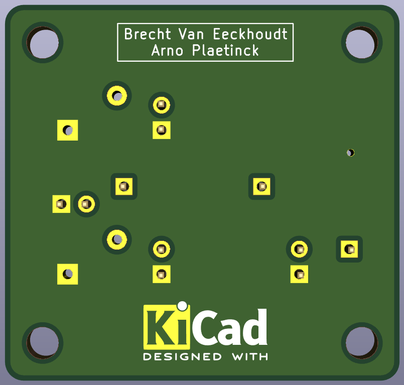
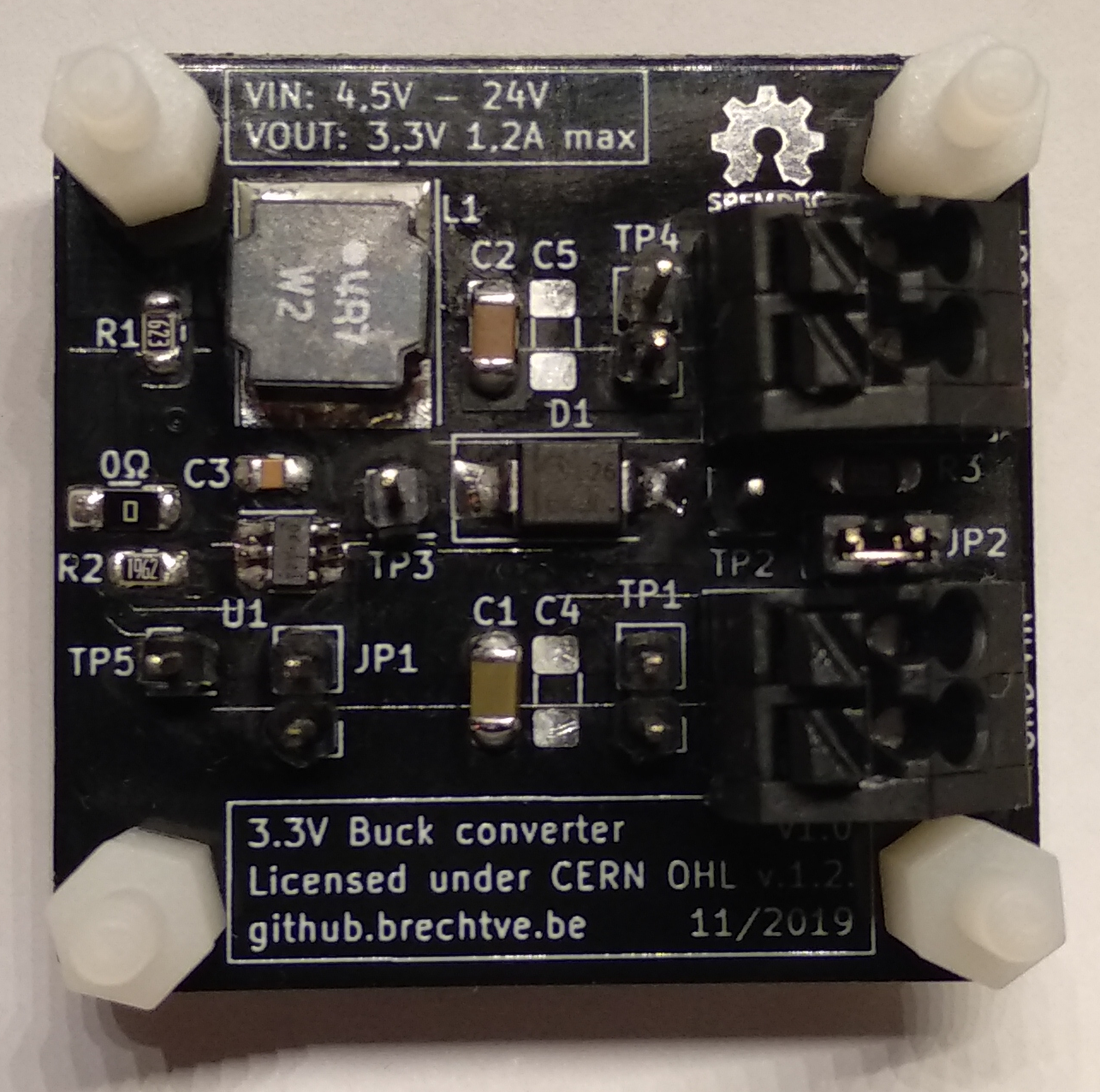
JP1 can be used to disable the buck converter.JP2 can be used to bypass the sense resistor R3 (measures the diode current).TPx) are given to be able to measure different voltages.C4 and C5 are footprints for extra capacitors if the signals have too much ripple.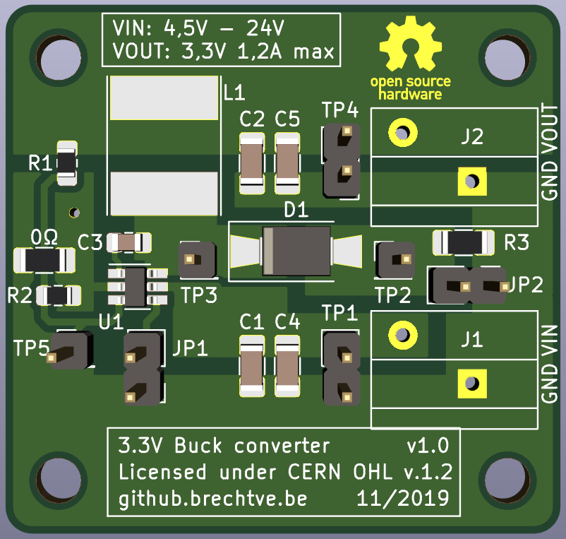
| Component | Value | Footprint | Other | Ordering |
|---|---|---|---|---|
| U1 | RT8259GE | SOT-23-6 | Richtek | |
| C1, C4 | 10 µF | 1206 | (X7R), 50V, 10% | Mouser.be |
| C2, C5 | 22 µF | 1206 | X7R, 10V, 10% | Mouser.be |
| C3 | 10 nF = 0,01 µF | 0805 | X7R, 50V, 10% | Mouser.be |
| D1 | If = 2A Vr = 40V Vf = 0,43V | SMA/SMB | Mouser.be | |
| L1 | 4,7 µH | NR8040 | Taiyo Yuden | Mouser.be |
| R1 | 62 kΩ | 0805 | 0,5% | Mouser.be |
| R2 | 19,6 kΩ | 0805 | 0,5% | Mouser.be |
| R3 | 0,1 Ω = 100 mΩ | 1206 | 1% | Mouser.be |
| 0Ω | 0 Ω | 1206 | Mouser.be | |
| J1, J2 | PTSA_1,5/_2-3,5-Z_BK | Pitch: 3,5 mm | 2 contacts, 250V 2A | Mouser.be |
WARNING: The pinout of J1 and J2 is reversed due to a footprint error (wrong top/bottom view). The Phoenix Contact connectors can however be manually separated and put back together in a way that they do fit on the board.
| Qty | Value | Footprint | References |
|---|---|---|---|
| 4 | M3 | MountingHole:MountingHole_3.2mm_M3 | H1, H2, H3, H4 |
| 3 | TestPoint | Connector_PinHeader_2.54mm:PinHeader_1x01_P2.54mm_Vertical | TP2, TP3, TP5 |
| 2 | 10 µF | Capacitor_SMD:C_1206_3216Metric_Pad1.42x1.75mm_HandSolder | C1, C4 |
| 2 | 22 µF | Capacitor_SMD:C_1206_3216Metric_Pad1.42x1.75mm_HandSolder | C2, C5 |
| 2 | Conn_01x02 | Connector_Phoenix_PTSA_extra:PhoenixContact_PTSA_1,5_2-G-3,5_1x02_P3.50mm_Angled | J1, J2 |
| 2 | TestPoint_2Pole | Connector_PinHeader_2.54mm:PinHeader_1x02_P2.54mm_Vertical | TP1, TP4 |
| 1 | 0,1 Ω | Resistor_SMD:R_1206_3216Metric_Pad1.42x1.75mm_HandSolder | R3 |
| 1 | 10 nF | Capacitor_SMD:C_0805_2012Metric_Pad1.15x1.40mm_HandSolder | C3 |
| 1 | 19,6 kΩ | Resistor_SMD:R_0805_2012Metric_Pad1.15x1.40mm_HandSolder | R2 |
| 1 | 4,7 µH | Inductor_SMD:L_Taiyo-Yuden_NR-80xx_HandSoldering | L1 |
| 1 | 62 kΩ | Resistor_SMD:R_0805_2012Metric_Pad1.15x1.40mm_HandSolder | R1 |
| 1 | D_Schottky_Small_ALT | Diode_SMD:D_SMA-SMB_Universal_Handsoldering | D1 |
| 1 | Jumper_NC_Small | Connector_PinHeader_2.54mm:PinHeader_1x02_P2.54mm_Vertical | JP2 |
| 1 | Jumper_NO_Small | Connector_PinHeader_2.54mm:PinHeader_1x02_P2.54mm_Vertical | JP1 |
| 1 | RT8259GE | Package_TO_SOT_SMD:SOT-23-6_Handsoldering | U1 |
| 1 | R_1206_3216Metric_Pad1.42x1.75mm_HandSolder | Resistor_SMD:R_1206_3216Metric_Pad1.42x1.75mm_HandSolder | 0Ω |
| 1 | Symbol_OSHW-EEVBLOG_SPFMDBC_10mm | BrechtVE_Aesthetics:OSHW-Logo_5.7x6mm_SolderMask | G1 |
The 26 most common of 27 parts.
It measures 40 × 38.1 mm and has 2 copper layers, 1.6 mm thick.
27 parts, built around the RT8259GE. The full list of its parts is on this page, with links to each part's symbol and footprint where PCBKit's library has them.
From the Fescron/Project-LabAnalogDesign2 repository on GitHub, at the commit this page was made from: the board is hardware/dc-dc-3-3V-RT8259GE/dc-dc-3-3V-RT8259GE.kicad_pcb. PCBKit opens the board in the browser, with nothing to install.
Its repository states no licence, so its author keeps all rights: ask Fescron before reusing the design.
freakontrol/stmbl
THE AUTHORS OF THIS SOFTWARE ACCEPT ABSOLUTELY NO LIABILITY FOR ANY HARM OR LOSS RESULTING FROM ITS USE. IT IS EXTREMELY UNWISE TO RELY ON SOFTWARE ALONE FOR SAFETY.

keer-nova74/STM32-Sumo-Robot-Controller-PCB
A robotics controller PCB project using an STM32 microcontroller, dual motor drivers, sensor interfaces, and power management, designed using KiCad.


hackclub/OnBoard
💡 Join 1,000 teenagers and make your first PCB with a $100 grant!

