2 layers
Nrf bga
github-linguist/linguist
Language Savant. If your repository's language is being reported incorrectly, send us a pull request!
12 parts14kMIT

 Fersaar/electrostatic_gripper
Project to develop a new gripper for handling thin metal foils without pneumatic
Elektrode v3 bipolar is an open-source printed circuit board by Fersaar, from the Fersaar/electrostatic_gripper repository on GitHub, published under the GPL-3.0 licence. It is a 2-layer board of 100 × 100 mm with 12 parts on 2 nets, routed with 9 tracks and 8 vias.
This project was developed as part of my academic studies, with the objective of creating a gripper specifically designed for handling thin lithium foil (less than 20 micrometers). Lithium is a highly reactive and sensitive material, which presents challenges when it comes to handling. Traditional methods, such as pneumatic grippers and large-area suction pads commonly used in film handling, are problematic because they would require the use of inert gas as the process medium. Additionally, pneumatic systems pose a risk of contaminating the foil with particles from the environment. As a result, electrostatic grippers offer a viable solution.
The underlying principle of the electrostatic gripper is that opposite electrical charges attract each other. When a voltage is applied to two parallel plates, an attractive force is generated between them (similar to the forces in a capacitor). Furthermore, a centering force is produced when the two plates are moved relative to one another.
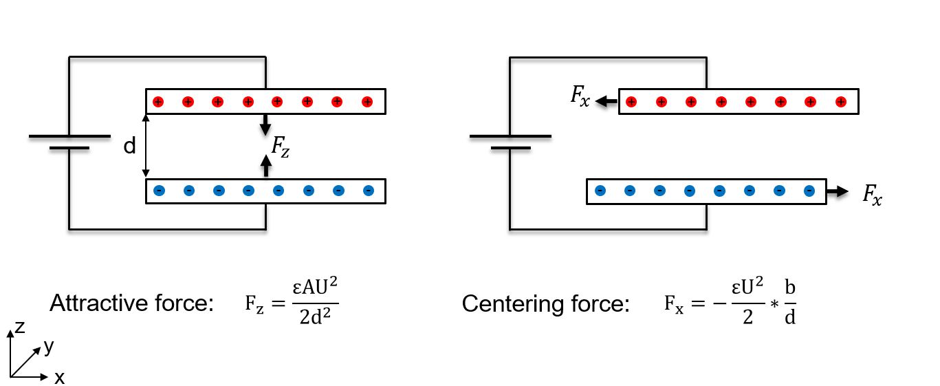
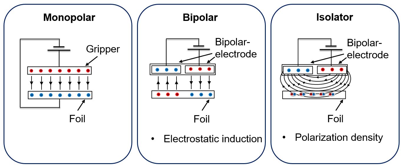
Based on this principle, various gripper designs can be developed. The simplest design, known as the monopolar gripper, operates on the concept of two parallel plates. In this configuration, one plate is formed by the gripper, while the second plate is represented by the foil being handled. A voltage is applied between the gripper and the foil.
In contrast, the bipolar design consists of two electrodes between which a voltage is applied. This setup induces movement in the electrically conductive foil. The gripper and the foil together form two capacitors connected in series. One advantage of this design is that the foil does not need to be electrically contacted or charged. However, the maximum achievable force is reduced by half, as the applied voltage is divided between the two capacitors.
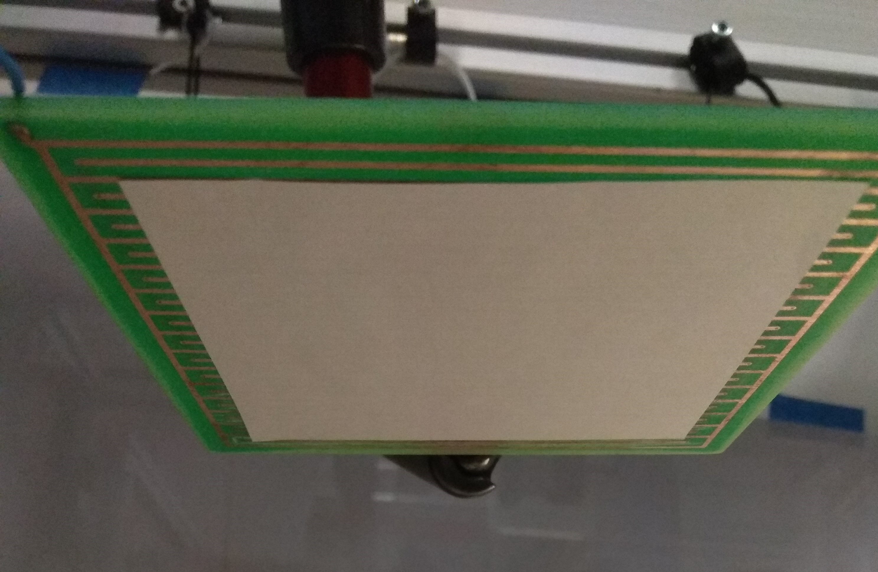
Furthermore, the bipolar design allows for the handling of non-conductive materials, such as paper. In this case, the force is generated through polarization rather than charge displacement. The individual molecules within the material align themselves with the electrostatic field produced by the gripper, forming dipoles. The force achievable with this method is lower than with conductive materials. Therefore, a strong electric field is particularly important, making an interdigitated design preferable. The reduced distance between opposing electrodes results in a higher electric field strength.
The gripper consists of two copper electrodes, each with an area of 70 x 35mm. The insulation distance between the two surfaces is 1 to 2 mm. A voltage of 1000 V is applied between the two electrodes.
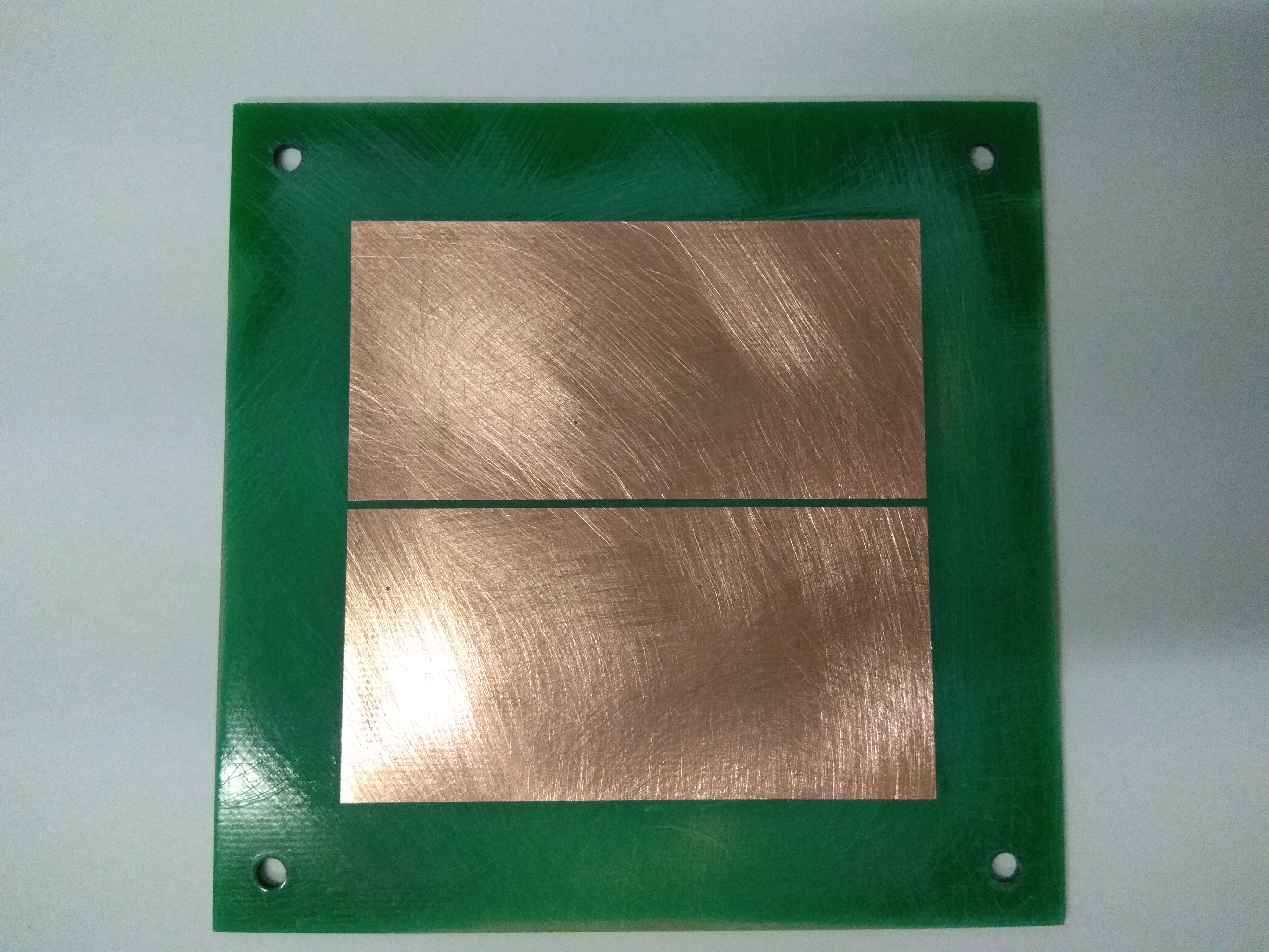 | 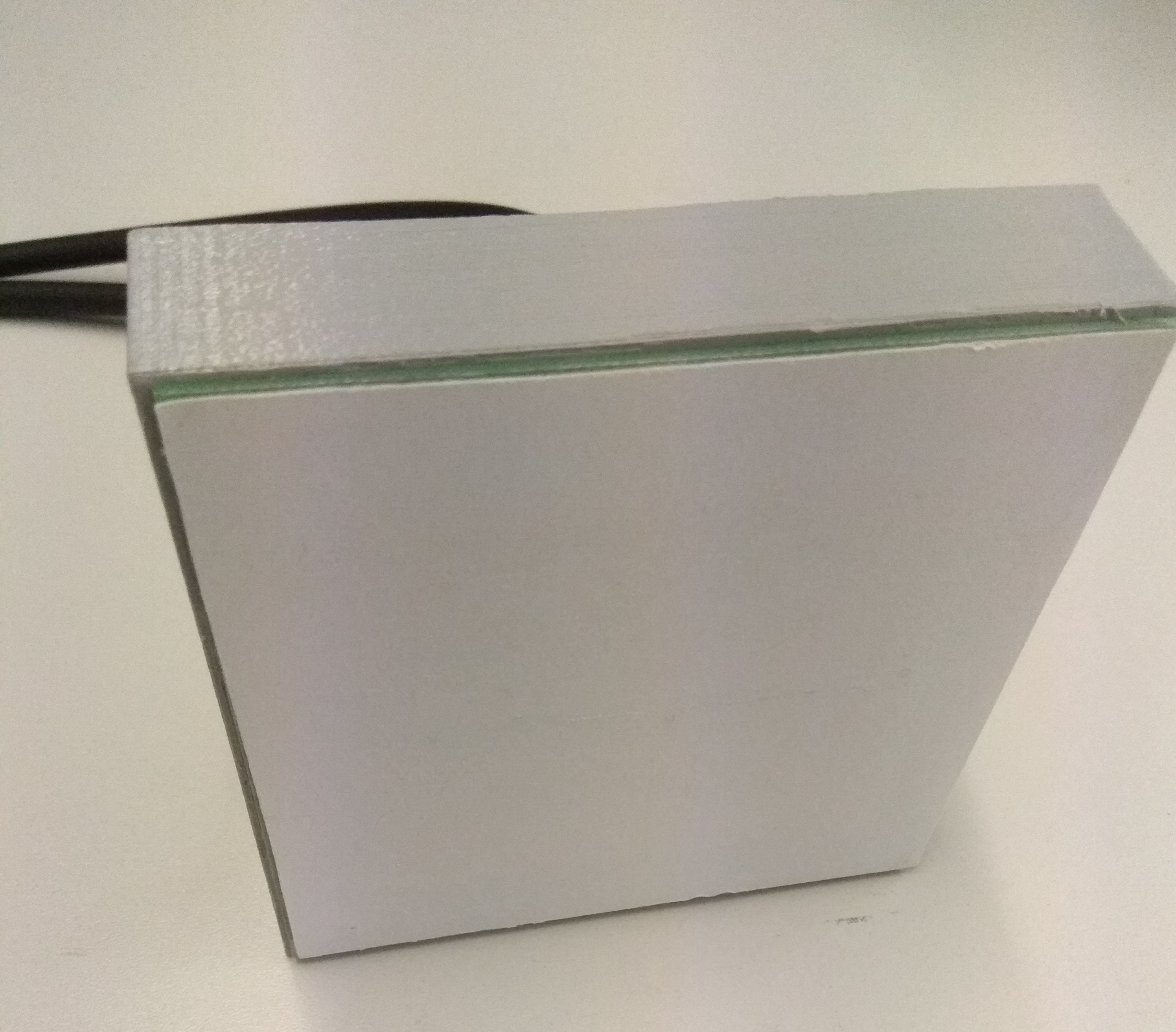 |
| gripper/board | gripper with housing and insulation |
Based on these findings, various materials were tested, and different disconnection strategies were explored. In addition to disconnecting the two electrodes from the power supply, the electrodes were switched to either a negative or positive state for shutdown. It was determined that lightly roughened paper was the most suitable material when combined with short-circuiting the two electrodes through the negative terminal of the power supply. This approach allowed for a switch-off time of less than one second.
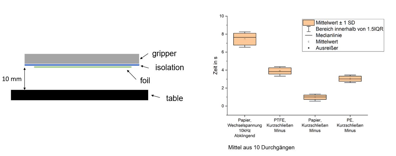 Release times with different insulation materials and shutdown methods
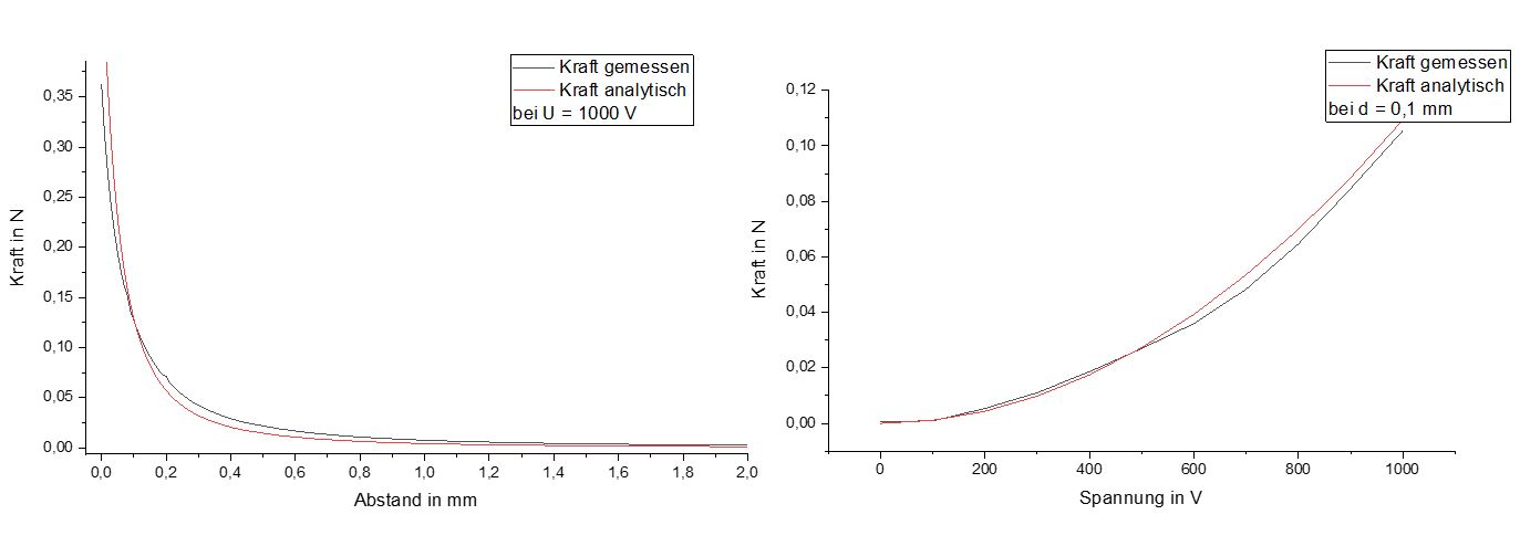
With a total electrode area of 70 x 70 mm, a maximum force of 0.35 N was achieved, which is approximately equivalent to 35 grams.
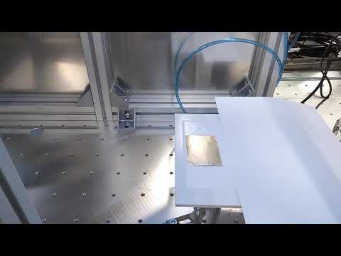
The practical application was successful:
Video:
Interdigitaldesign for e.g. paper:
| Qty | Value | Footprint | References |
|---|---|---|---|
| 4 | + | Wire_Pads:SolderWirePad_single_SMD_3x5mm | J1, J1, J1, J1 |
| 4 | - | Wire_Pads:SolderWirePad_single_SMD_3x5mm | J2, J2, J2, J2 |
The 8 most common of 12 parts.
It measures 100 × 100 mm and has 2 copper layers, 1.6 mm thick.
12 parts. The full list of its parts is on this page, with links to each part's symbol and footprint where PCBKit's library has them.
From the Fersaar/electrostatic_gripper repository on GitHub, at the commit this page was made from: the board is Kicad/elektrode_v3_bipolar/elektrode_v3_bipolar.kicad_pcb. PCBKit opens the board in the browser, with nothing to install.
Its repository publishes it under the GPL-3.0 licence: you may reuse it on that licence's terms (keep the author's notice, and for a copyleft licence share your changes alike).
github-linguist/linguist
Language Savant. If your repository's language is being reported incorrectly, send us a pull request!


google/mozc-devices
Circuit diagrams and firmware source code for Gboard DIY keyboards


hackclub/OnBoard
💡 Join 1,000 teenagers and make your first PCB with a $100 grant!

VoronDesign/Voron-Tap
Tap is a nozzle-based z-probe for the V2 and Trident printer designs. The entire toolhead moves to trigger an optical switch. Tap offers many advantages:

stacksmashing/pico-tpmsniffer
A simple, very experimental TPM sniffer for LPC bus