Skip to the content
PCBKitNew board
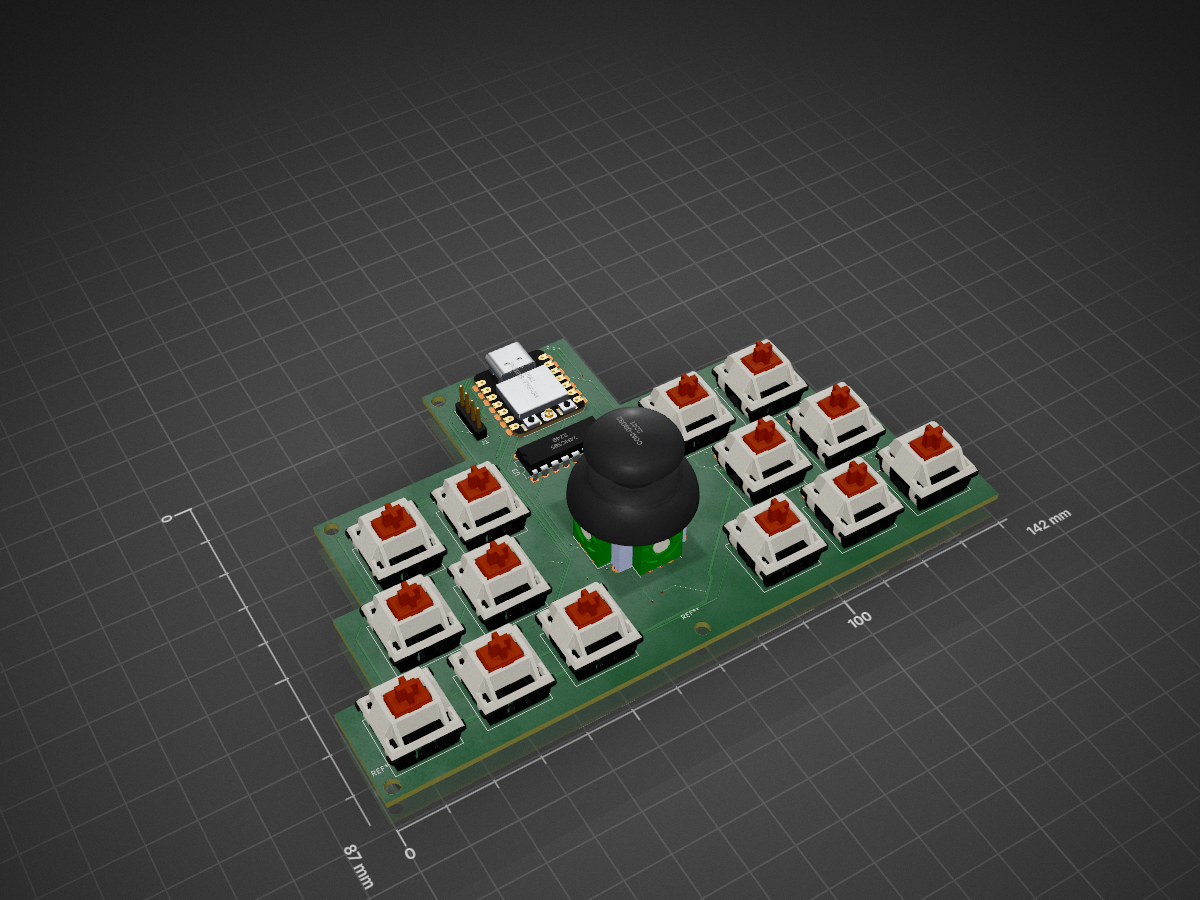
2 layers142 × 87 mmHackPad, the printed circuit board in 3D

An Elevated "SteamDeck" for developpers with fully customizable controls across many programs. I made it to make my life easier by having all of the most used tools and a way to properly move in CAD using the joystick…

Size
142 × 87 mm
Copper layers
2
Thickness
1.6 mm
Parts
41
Nets
39
Pads
176
Tracks, vias
359, 33
Routed
Yes
KiCad
KiCad 10.0 (file 20260206)
Created
5 Jul 2026
Updated
12 Aug 2026

Overview

HackPad is an open-source printed circuit board by fayekdev, from the fayekdev/HackPad repository on GitHub. It is a 2-layer board of 142 × 87 mm with 41 parts on 39 nets, routed with 359 tracks and 33 vias.

It is built around the 74HC595 and COM-09032. Its parts include 16 diodes, 15 switches, 3 ICs and 1 connector. It belongs with the lEDs and displays boards of this library.

Main components

2

README

README.md

.devPAD

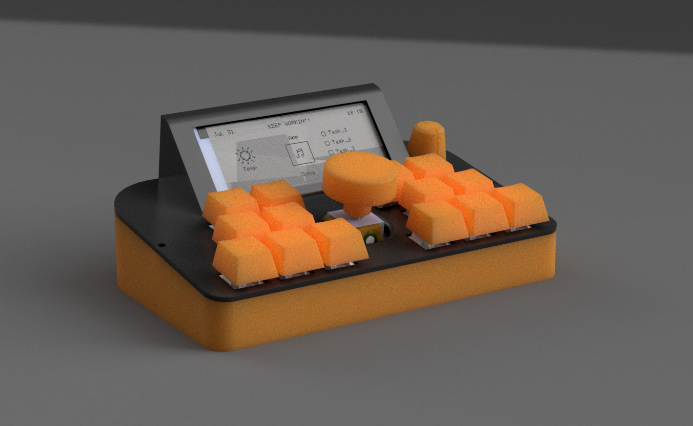
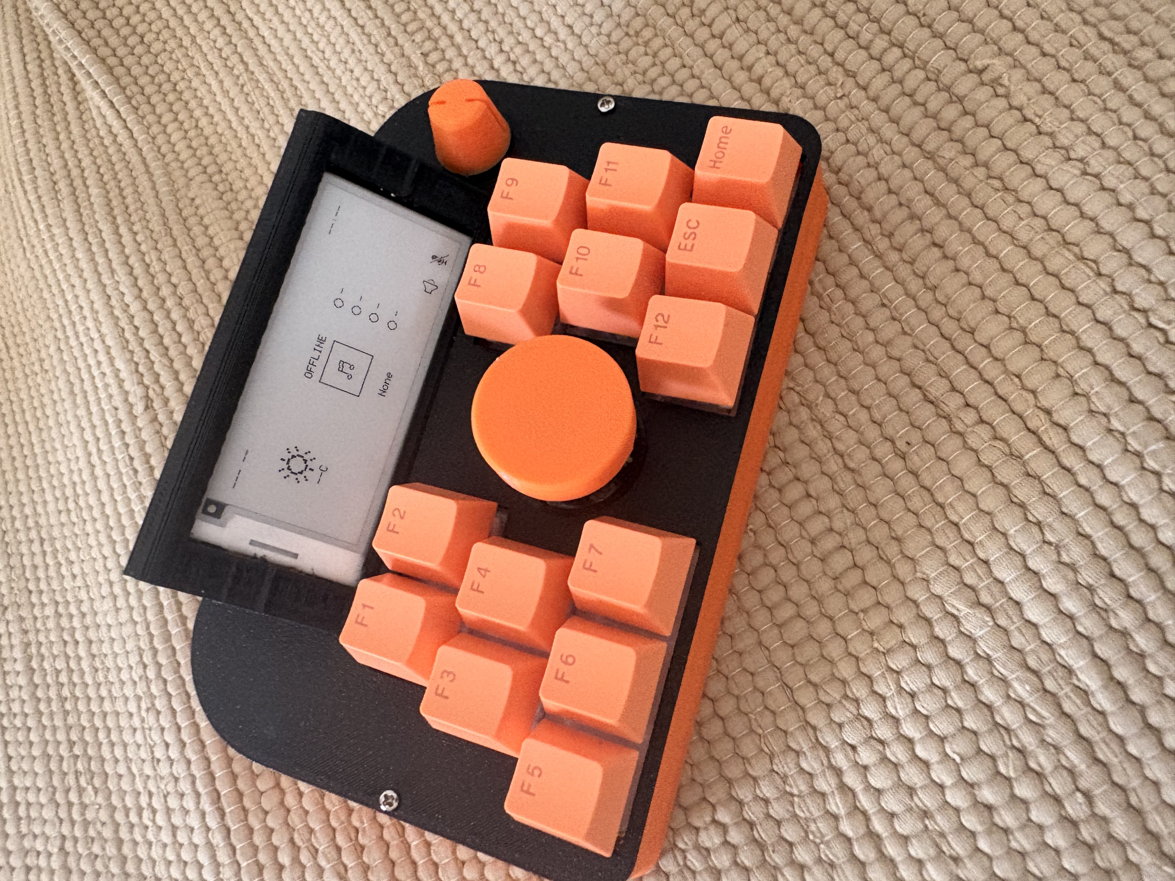
An Elevated "SteamDeck" for developpers with fully customizable controls across many programs. I made it to make my life easier by having all of the most used tools and a way to properly move in CAD using the joystick in the middle. The e-ink screen is used as clock and a to-do list and could display the current media, volume level, microphone status and temperature.

the tech stack

Python

CPP

Fusion360

KiCAD

Screenshots

Render

Physical

THE CODE

The code is still incomplete but still has ~80% functionality(only a few minor changes to make)

Currently working on the hardware problems so it is on delay

How was it made

  • I designed the PCB in KiCAD and exported to Fusion to model the Case.

  • The case was modeled and the components too to ensure the fit is correct

  • Printed the first version

  • Fixed the errors in V1 and added a few features.

  • The PCB arrived and all components were test fit

  • Began soldering the PCB

  • Fixed the errors I had made and uploaded a few test sketches.

  • Test sketches were success and I tested the production code

  • Production code worked out fine with a few problems

  • A wire connected the screen to the microcontroller snapped and when trying to fix it a short-circuit happened and probably caused the microcontroller to malfunction.

(The device only worked for 30 minutes or so before breaking)

AI disclosure

  • AI was used as a research tool where I gave it all my requirements in one and it generated some sort of documentation that was held in it's context window so that when I ask a question or have a concern it automatically gives the answer I need instead of losing a ton of time researching myself

  • Another usecase is the few errors I stumble upon that I spent a ton of time trying to fix I give to AI to give me a suggestion on how to fix it

Installation

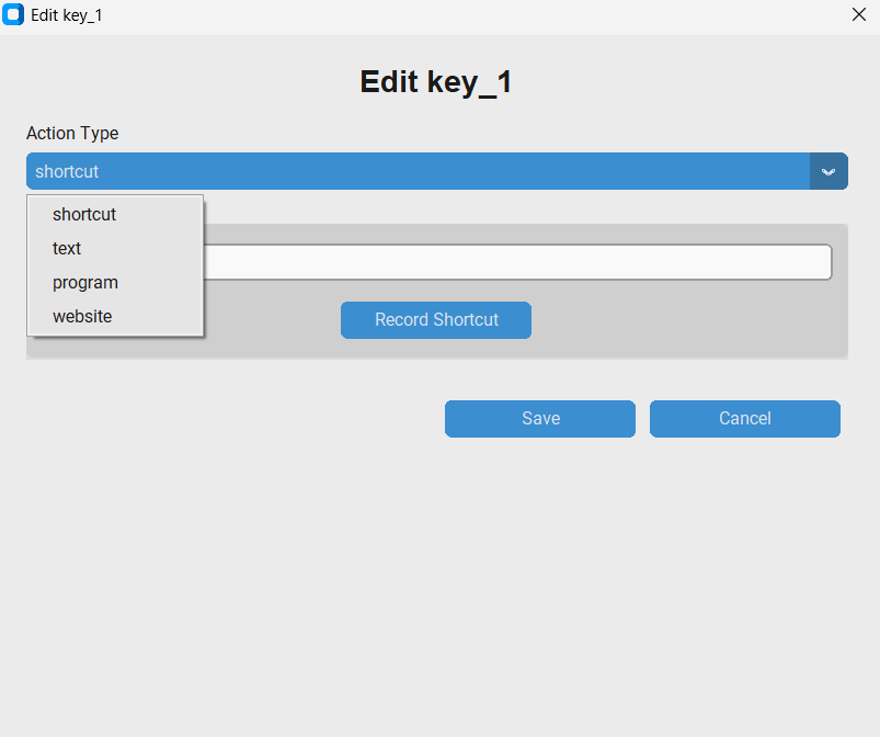
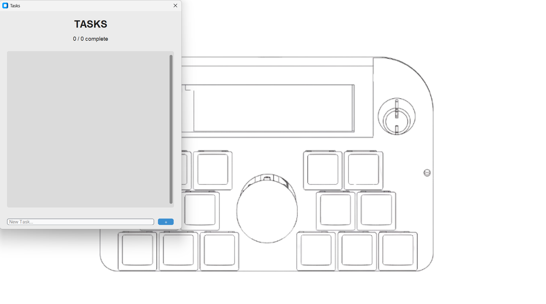
Install the .devPAD desktop app -->

Install

Upload the main.ino sketch to the microcontroller

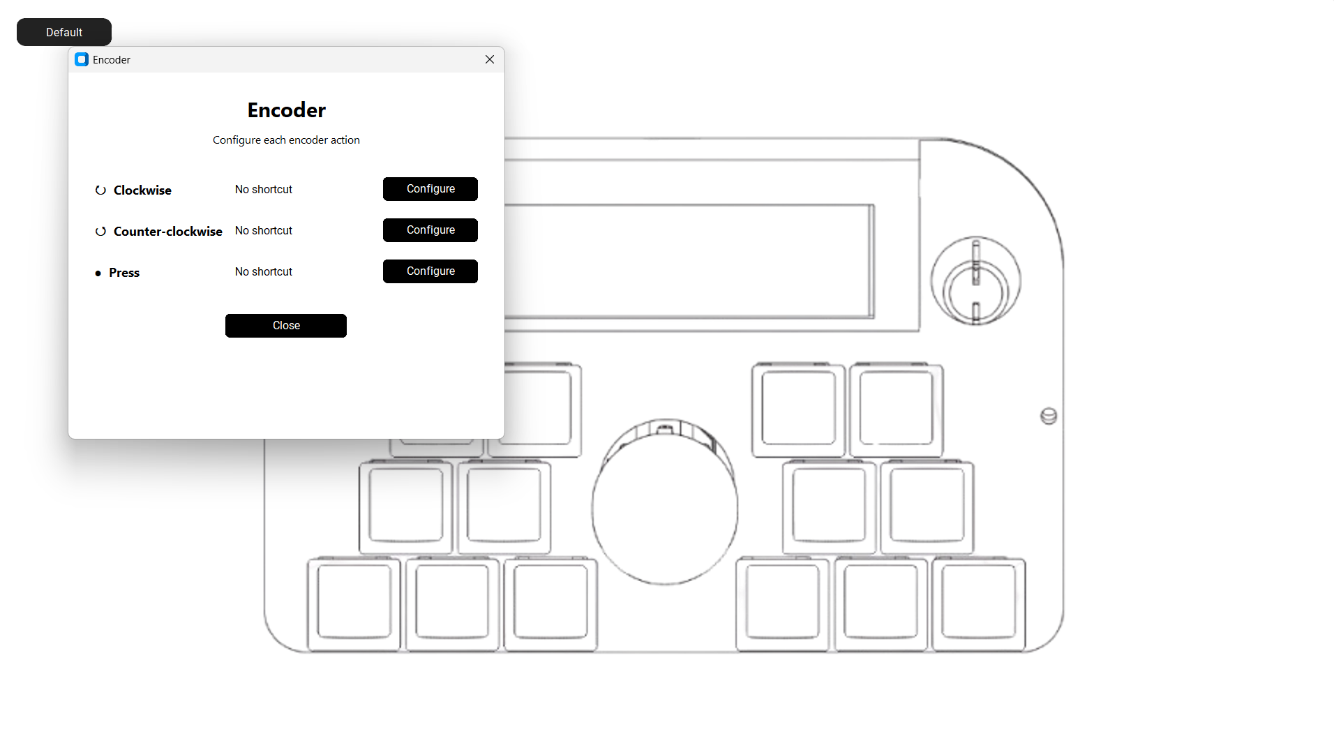
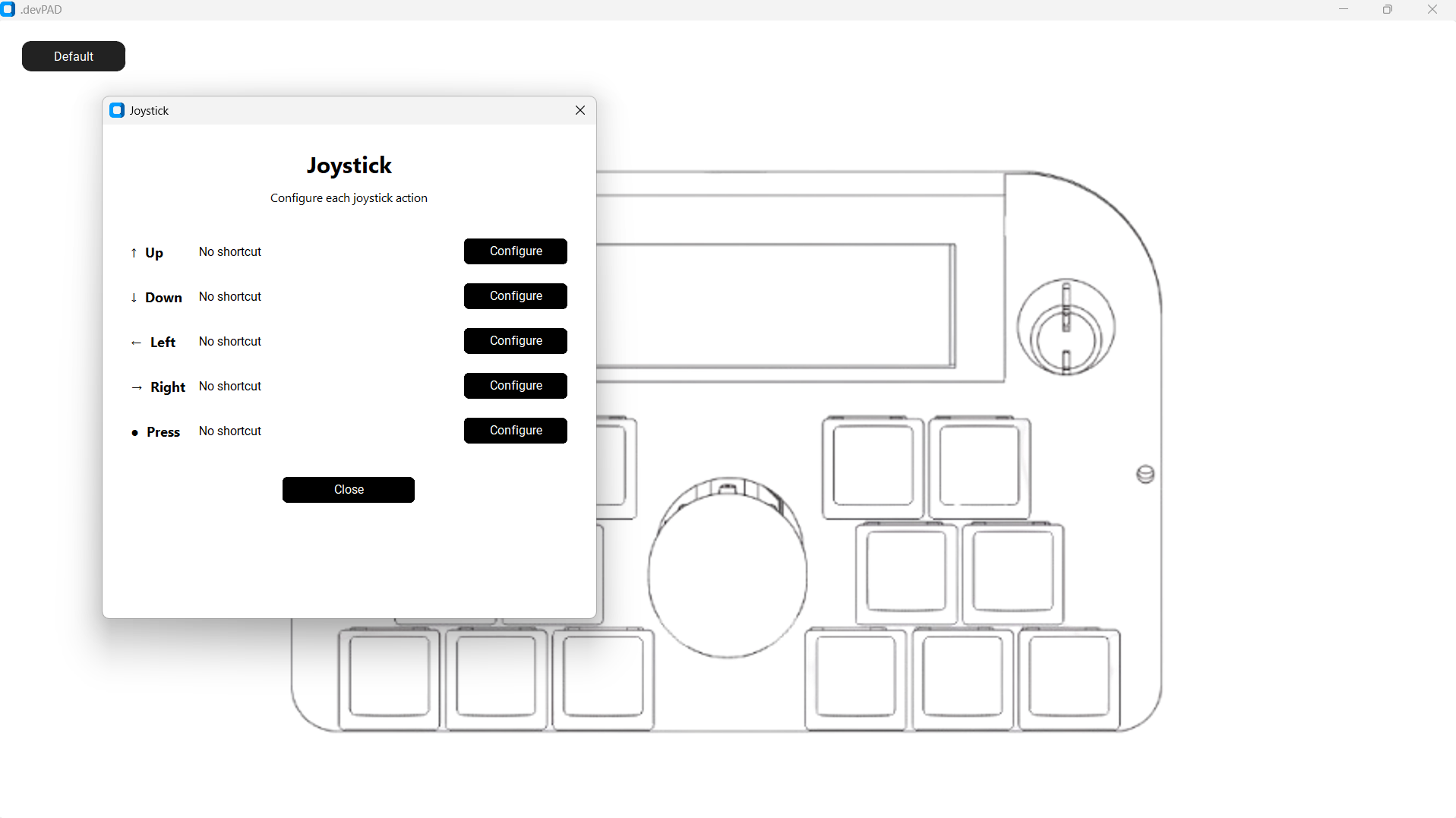
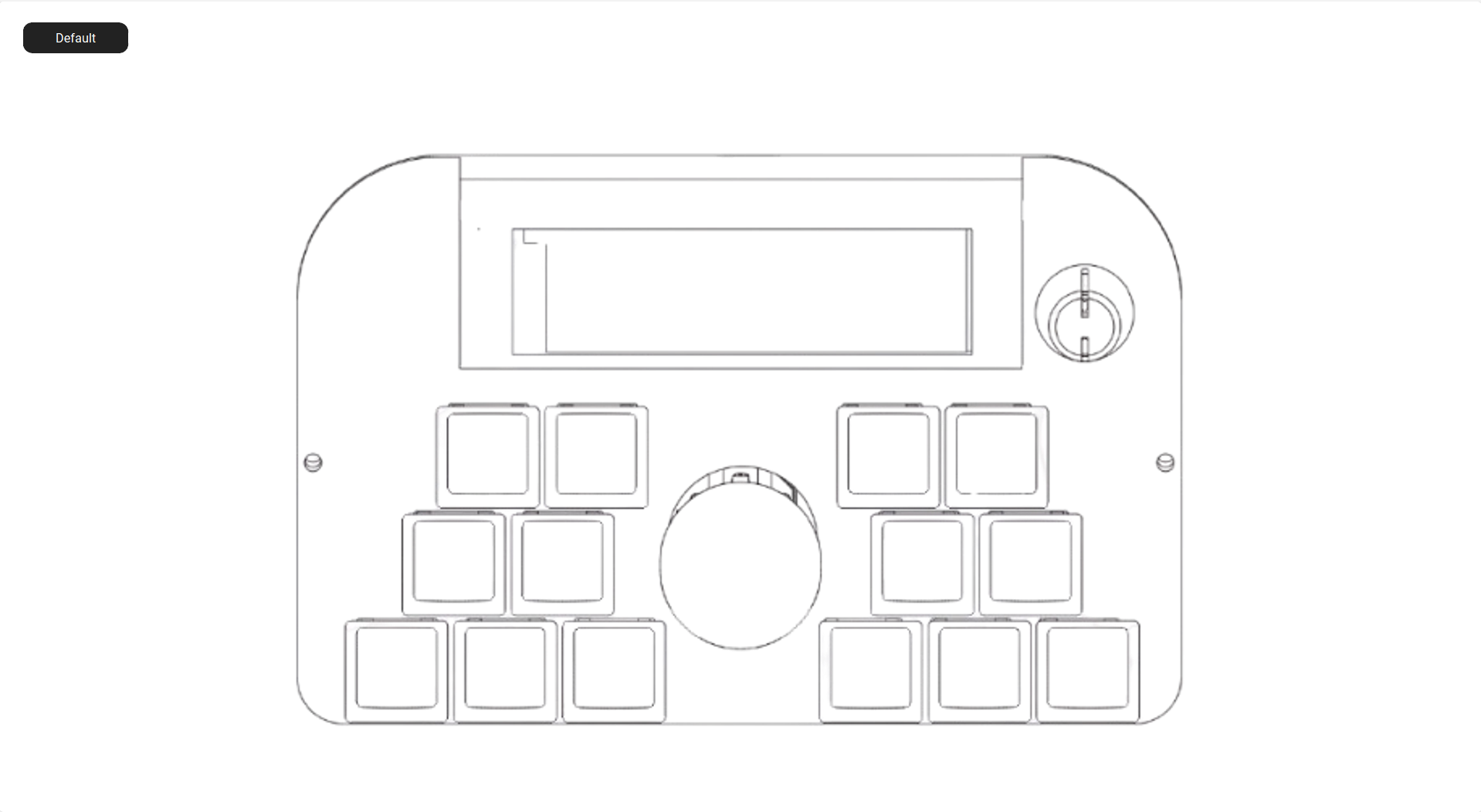
SCREENSHOTS OF THE APP
APP

APP

APP

APP

APP

BOM

ComponentQty
Xiao ESP32 C31
Keycaps14
We-Act studio 2.9" E-ink screen1
M2x6 screws8
MX-Cherr Keyswitches14
1N4148 diodes16
Rotary encoder1
Joystick1
Wire(as much as you need)
SN74HC595N1
PCB1

TOOLS

  • Access to a 3D printer & filament
  • Soldering tools
  • Wire strippers
  • USB-C wire
  • Arduino IDE

Assembly GUIDE

  1. Print all of the components. The face plate cover is optional (you should glue it if you want to use it)

  1. Solder the first diode (under the joystick) upside down then solder the rest upright.

  1. Solder the Joystick in its respective place but make sure it is properly level.

  1. Solder the SN74HC595 and the Xiao ESP32 C3.

  1. Solder all of the keyswitches.

  1. Screw in the encoder and seat in the screen (if you want to make sure it's even more secure, use some tape instead of using the support beam).

  1. Solder all of the encoder wires from the bottom and solder them to the encoder.

  1. Solder the screen using it's respective connections using the schematic as a reference PS: The purple wire is not needed and the orange one should be wired up to the RST switch.

  1. Seat the PCB and screw it in.

  1. Close up the top plate being careful that the wires don't interfere with the USB port. You could put the USB-C wire in and close up the top plate to keep the wires from interfering

  1. Add the joystick, the encoder knob and the 14 keycaps.

  1. Upload the main.ino sketch via the Arduino IDE and run the ".devPAD" app
Parts

41
QtyValueFootprintReferences
16DDiode_THT:D_DO-35_SOD27_P7.62mm_HorizontalD1, D2, D3, D4, D5, D6, D7, D8, D9, D10, D11, D12, D13, D14, D15, D16
14SW_PushButton_Switch_Keyboard:SW_Cherry_MX_1.00u_PCBSW1, SW2, SW3, SW4, SW5, SW6, SW7, SW8, SW9, SW10, SW11, SW12, SW13, SW14
174HC595Package_DIP:DIP-16_W7.62mmU3
1COM-09032COM-09032:XDCR_COM-09032U2
1Conn_01x04_PinConnector_PinHeader_2.54mm:PinHeader_1x04_P2.54mm_VerticalJ1
1MOUDLE-SEEEDUINO-XIAORF_Module:MCU_Seeed_ESP32C3U1
1RotaryEncoder_Switch_MPRotary_Encoder:RotaryEncoder_Alps_EC11E-Switch_Vertical_H20mmSW15

The 35 most common of 41 parts.

Questions

How big is the HackPad PCB?

It measures 142 × 87 mm and has 2 copper layers, 1.6 mm thick.

What parts does the HackPad use?

41 parts, built around the 74HC595 and COM-09032. The full list of its parts is on this page, with links to each part's symbol and footprint where PCBKit's library has them.

Where can I download the HackPad KiCad files?

From the fayekdev/HackPad repository on GitHub, at the commit this page was made from: the board is KICAD/HackPad.kicad_pcb and its schematic KICAD/HackPad.kicad_sch. PCBKit opens the board in the browser, with nothing to install.

Can I use the HackPad design in my own project?

Its repository states no licence, so its author keeps all rights: ask fayekdev before reusing the design.

Similar boards

  • 2 layers298.9 × 151.4 mmErgo unibody, the printed circuit board in 3D

    Ergo unibody

    aidancahill/custom-keyboard

    A 54-key split ergonomic keyboard with analog joysticks, shift register matrix scanning, and a Seeeduino XIAO nRF52840 BLE microcontroller. Designed from scratch using Ergogen, KiCad, and ZMK firmware.

    132 partsMIT
  • 2 layers140 × 71 mmOpen game pad classic, the printed circuit board in 3D

    Open game pad classic

    not-forest/open-game-pad

    An open-source, low-cost, DIY Game-Pad

    57 partsMIT
  • 2 layers304.8 × 95.2 mmLMN, the printed circuit board in 3D

    LMN

    FundamentalFrequency/LMN-3-ECAD

    Electrical CAD Files for the LMN-3 Project

    106 parts106CC-BY-SA-4.0
  • 2 layers27.3 × 34.3 mmPs4, the printed circuit board in 3D

    Ps4

    little-scale/PS4_joystick_footprint

    PS4 Joystick Footprint for Kicad

    6 parts18
  • 2 layers235.8 × 117.2 mmErgorox50, the printed circuit board in 3D

    Ergorox50

    ReGenBot03/Ergorox50

    Personal Split Keyboard Project with Thumstick & Trackpad

    197 parts13
  • 2 layers130 × 109 mmRight, the printed circuit board in 3D

    Right

    Hex-4/glyph

    [ a custom split keyboard for portably and comfortably interfacing with computing systems ]

    49 parts11MIT
  • 2 layers107 × 83 mmHEX remote, the printed circuit board in 3D

    HEX remote

    Josh4minee/HEX-B12.V1

    HEX-B12.V120 is a custom designed hexapod using mg996r servos and has it's theme based on the beloved bot B-12 from the popular video game STRAY.

    16 parts7MIT
  • 2 layers268.4 × 63.2 mmProject Hermes, the printed circuit board in 3D

    Project Hermes

    shiva233/Project-Hermes

    Project Hermes is a handheld "console" designed for people who already own gaming PCs so they can stream their games via SteamLink so they can take it anywhere for cheap!

    17 parts4