2 layers37 × 19 mm
Passive rpi hub75-adapter
hzeller/rpi-rgb-led-matrix
Controlling up to three chains of 64x64, 32x32, 16x32 or similar RGB LED displays using Raspberry Pi GPIO
2 parts4.4kGPL-2.0

 fangyizhang-x/inst-obj2
This repository provides the designs and codes for our paper "Towards assessing compliant robotic grasping from first-object perspective via instrumented objects".
TMAG5273A1 PCB mini is an open-source printed circuit board by fangyizhang-x, from the fangyizhang-x/inst-obj repository on GitHub, published under the Apache-2.0 licence. It is a 2-layer board of 6.6 × 6.2 mm with 2 parts on 5 nets, routed with 13 tracks and 0 vias.
Its parts include 1 capacitor and 1 IC.
Project page for the paper "Towards assessing compliant robotic grasping from first-object perspective via instrumented objects", published in the journal RA-L.
@ARTICLE{10538419,
  author={Knopke, Maceon and Zhu, Liguo and Corke, Peter and Zhang, Fangyi},
  journal={IEEE Robotics and Automation Letters},
  title={Towards Assessing Compliant Robotic Grasping From First-Object Perspective via Instrumented Objects},
  year={2024},
  volume={9},
  number={7},
  pages={6320-6327},
  keywords={Sensors;Faces;Magnetic sensors;Force;Magnets;Grasping;Three-dimensional displays;Grasping;methods and tools for robot system design;soft sensors and actuators},
  doi={10.1109/LRA.2024.3405371}}
Please refer to the paper via IEEE or arXiv for more details.
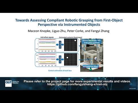
For fabrication details, please refer to the fabrication readme.
For the contact estimation, codes and data are in Contact_Estimation.
The full results for the other four faces can be seen in detailed_results_for_the_other_four_faces.pdf.

A comparison was made to a baseline linear regression method, whose results are shown in the above table. The linear regression has very poor performance in all metrics, indicating it is not suitable for modeling such complex non-linear mapping from Hall-effect signals to contact forces. The fully-connected network used in this work is just a proof of concept for data-driven contact estimation via Hall-effect signals. We do not claim the optimality of the neural network used in the paper and it is worth exploring more appropriate machine learning methods for different observations in future works and all feasible solutions will help scale the application of instrumented compliant objects for robotic grasping performance assessment.
As discussed in Section VII, studies in Section V-E and Section V-F showed that the location coverage of training data is critical for better contact location/case estimation accuracy, while much less data (2683 samples in total, and about 19 samples for each contact location/case) can enable accurate contact force estimation. In future training/calibration data collection, a better balance can be achieved by collecting less data for each contact location/case but covering as many contact locations and numbers of contacts as possible.
As introduced in the Introduction of the paper, this work is motivated to assess robotic grasping of compliant objects by measuring the stress or damage from a first-object perspective using mock objects (instrumented compliant objects). From a mock-compliant object perspective, the possibility of extending a design for different properties (such as hardness and shapes) and for providing different observations (such as contact force, deformation, and shape changes) is critical. Therefore, as a proof of concept, this paper adopts:
However, as discussed in the paper, we do not claim the current design’s optimality. More designs are worth exploring in future works and all feasible designs (including variants of the work by Kıiva et al) will help to extend the application of instrumented objects for assessing the grasping of various compliant objects. If only 2D tactile pressure is needed, some off-the-shelf sensor films could be a good option, such as a tactile pressure indicating sensor film (https://www.sensorprod.com/index.php).
As discussed in Section IV in the paper, if more or less deformation is needed, different properties including the hardness of the instrumented object can be achieved by using different materials such as silicone with different levels of hardness for the outer shell. By adjusting this hardness, the deformation measured by the sensors can be tailored to match specific scenarios. The Shore hardness scale ranges from soft rubbers and gels (Shore 00), soft to semi-rigid rubbers (Shore A) and hard rubbers/plastics (Shore D). In this paper, all experiments utilized a shell made from Platsil GEL-10 Prosthetic Grade Silicone, which has a Shore hardness of A10. Shore A10 was chosen because it provides firmness, simplifying prototype design and testing, while still allowing elastic deformation under reasonable force (e.g., pinching or firm pressing). This hardness can produce deformation for detecting as little as 0.12N contact force changes. Switching to a silicone with lower Shore hardness (e.g., Shore 0010-0030) is expected to increase sensitivity, but would result in a lower readable maximum force. Increasing the hardness would decrease the sensitivity, while allowing for a higher range of applied force. Conversely, increasing hardness too much into the mid Shore D range could lead to inaccurate readings due to deformation of the plastic inner core and PCBs.
While silicone is suggested due to its elastic properties and ease of use, alternative elastomers could also be used, such as Thermoplastic Polyurethane (TPU), which can be 3D printed using FDM and SLS technologies. TPU offers a large hardness range, commonly measured at Shore 60A-90A, although some variants can be as low as Shore 0030. Elastic resins are also available for resin 3D printers, with a hardness of around Shore 50-80A.
The current design generally worked well in contact estimation, although there were some design drawbacks that caused non-trivial performance degradation with simultaneous contacts from multiple faces and the internal core shifting w.r.t. the silicone shell between calibration and evaluation.
This concept and design can be extended in the future for more comprehensive measurements of compliant robotic grasping (such as the measurement of 3D contact force and more simultaneous contact points, and the estimation of deformation and shape changes) with various robotic grippers (such as anthropomorphic robotic hands and soft robotic grippers/hands). Ultimately this could lead to a robust framework for autonomously generating designs of instrumented objects with various measurement capabilities and physical properties (shapes, sizes, stiffness, etc) for benchmark purposes. Such instrumented objects could close the loop of developing/learning solutions for different compliant robotic manipulation tasks by providing timely and accurate feedback from a first-object perspective.
To be used for assessing soft robotic grippers/hands, the design might need to be adjusted in three aspects:
This instrumented object can be extended for assessing grasping by anthropomorphic robotic hands, but needs additional training data to cover situations different from the three types of probes currently used for training data collection. For better and stabler performance, the current design also needs to be optimized to eliminate the Problems a) and b) discussed in Section VII in the paper.
| Qty | Value | Footprint | References |
|---|---|---|---|
| 1 | C_Small | Capacitor_SMD:C_0805_2012Metric | C1 |
| 1 | TMAG5273 | Package_TO_SOT_SMD:SOT-23-6 | U1 |
hzeller/rpi-rgb-led-matrix
Controlling up to three chains of 64x64, 32x32, 16x32 or similar RGB LED displays using Raspberry Pi GPIO


adamws/kicad-kbplacer
KiCad plugin for automatic keyboard's key placement and routing

Luos-io/luos_engine
Open-source and real-time orchestrator for cyber-physical-systems, to easily design, test and deploy embedded applications and digital twins.

NVNTLabs/switch2-SDEX2M2
Micro SD Express to M.2 NVME Adapter for Nintendo Switch 2

BlueSCSI/BlueSCSI-v2
BlueSCSI v2/Ultra - an open source, open hardware, SCSI emulator using the Pi Pico PR2040 and Pico 2 RP2350

ohmtech-rdi/eurorack-blocks
Software to Hardware Prototyping for Eurorack using C++, Max/Gen~ or Faust

It measures 6.6 × 6.2 mm and has 2 copper layers, 1.6 mm thick.
2 parts. The full list of its parts is on this page, with links to each part's symbol and footprint where PCBKit's library has them.
From the fangyizhang-x/inst-obj repository on GitHub, at the commit this page was made from: the board is PCB/TMAG5273A1_PCB_mini/TMAG5273A1_PCB_mini.kicad_pcb and its schematic PCB/TMAG5273A1_PCB_mini/External_sensor_schematic/External_sensor_schematic.kicad_sch. PCBKit opens the board in the browser, with nothing to install.
Its repository publishes it under the Apache-2.0 licence: you may reuse it on that licence's terms (keep the author's notice, and for a copyleft licence share your changes alike).