2 layers56 × 65 mm
SeaTalk1
dotnet/iot
This repo includes .NET Core implementations for various IoT boards, chips, displays and PCBs.
24 parts2.4kMIT
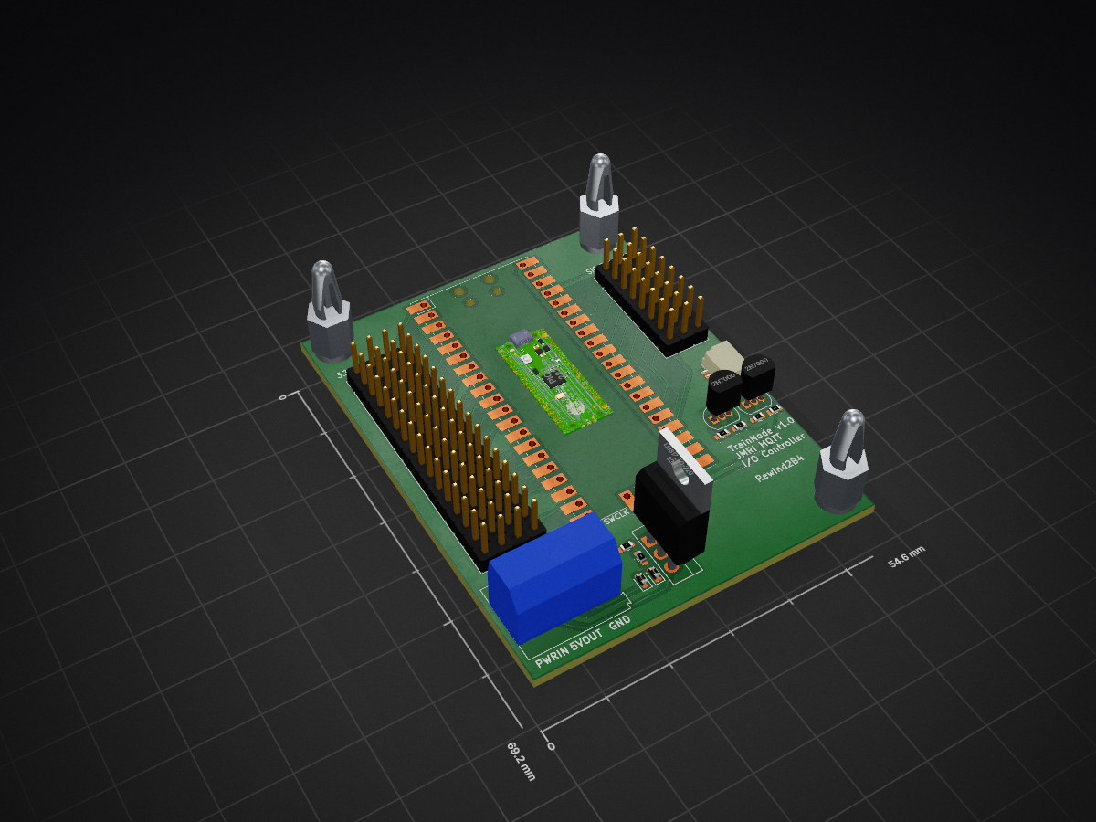
 fallbotics/JMRITrainNode1
TrainNode is a JMRI compatible I/O controller built on the MQTT protocol. Using the Raspberry Pi Pico, the board can support up to 16 turnouts
MQTTDecoderExpansionBoard is an open-source printed circuit board by fallbotics, from the fallbotics/JMRITrainNode repository on GitHub, published under the GPL-3.0 licence. It is a 2-layer board of 54.6 × 69.2 mm with 24 parts on 43 nets, routed with 202 tracks and 2 vias.
Its parts include 9 connectors, 6 resistors, 2 ICs, 2 diodes and 2 transistors. It belongs with the RP2040 boards of this library.
TrainNode is a JMRI compatible I/O controller built on the MQTT protocol. Using the Raspberry Pi Pico, each node can support up to 16 turnouts as standard, or more with user addons.
This project uses the Wiznet Ethernet Hat for the Raspberry Pi Pico (RP2040), which is available at major retailers such as Core Electronics in Australia. This is used for networking. The Pico-W is unsupported at this time.
General Settings "server_addr": IP address of the MQTT server "client_name": The client name of the node "MQTT_user": The username of the MQTT server "MQTT_password": The password of the MQTT server "MQTT_port": The port the MQTT server is on "neopixel_pin": The GPIO pin that any neopixels are connected to (ignored when 0 neopixels) "neopixel_count": The number of neopixels attached to the node (put 0 for no neopixels) "device_poll_timeout_ms": The amount of time that the system waits for interupts such as button releases when pressed "max_ip_connect_attempts": The amount of times the node will attempt to connect before powering off (requiring a power cycle)
Device Settings (see example_json for usage)
The device settings looks as follows:
"address": "jmri/track/turnout/4", "current_state": { "state": "CLOSED", "position": 0 }, "states": { "THROWN": [255, 0, 0], "CLOSED": [0, 255, 0] }, "io": "OUTPUT", "type": "neopixel", "args": { }
Where, "address": "jmri/track/turnout/4", "current_state": wrapper for "state" and "position" (Do not modify) "state": The current state of the device (this is updated in real time), eg. "THROWN" "position": The current position of the device (this is updated in real time), eg. [255, 0, 0] "states": The messages that JMRI will send and the response position, eg. "THROWN": [255, 0, 0], "CLOSED": [0, 255, 0] "io": Whether the device is an INPUT or an OUTPUT "type": The device type (see list below) "args": Any other arguments required by the device (see arguments in list below)
Available Device Types
| Qty | Value | Footprint | References |
|---|---|---|---|
| 4 | 1000 | Resistor_SMD:R_0603_1608Metric | R3, R4, R5, R6 |
| 4 | Conn_01x16_Female | Connector_PinHeader_2.54mm:PinHeader_1x16_P2.54mm_Vertical | J2, J4, J5, J6 |
| 3 | Conn_01x08_Female | Connector_PinHeader_2.54mm:PinHeader_1x08_P2.54mm_Vertical | J1, J3, J8 |
| 2 | 1N4007 | Diode_SMD:D_0603_1608Metric | D1, D2 |
| 2 | 2N7000 | Package_TO_SOT_THT:TO-92_Inline | Q2, Q3 |
| 1 | 1200 | Resistor_SMD:R_0603_1608Metric | R2 |
| 1 | 330 | Resistor_SMD:R_0603_1608Metric | R1 |
| 1 | Conn_01x03_Female | TerminalBlock:TerminalBlock_Altech_AK300-3_P5.00mm | J12 |
| 1 | Conn_01x04_Socket | Connector_JST:JST_SH_SM04B-SRSS-TB_1x04-1MP_P1.00mm_Horizontal | J9 |
| 1 | LM317_TO-220 | Package_TO_SOT_THT:TO-220-3_Vertical | U2 |
| 1 | Pico | MCU_RaspberryPi_and_Boards:RPi_Pico_SMD_TH | U1 |
The 21 most common of 24 parts.
It measures 54.6 × 69.2 mm and has 2 copper layers, 1.6 mm thick.
24 parts. The full list of its parts is on this page, with links to each part's symbol and footprint where PCBKit's library has them.
From the fallbotics/JMRITrainNode repository on GitHub, at the commit this page was made from: the board is PCB/MQTTDecoderExpansionBoard.kicad_pcb and its schematic PCB/MQTTDecoderExpansionBoard.kicad_sch. PCBKit opens the board in the browser, with nothing to install.
Its repository publishes it under the GPL-3.0 licence: you may reuse it on that licence's terms (keep the author's notice, and for a copyleft licence share your changes alike).
dotnet/iot
This repo includes .NET Core implementations for various IoT boards, chips, displays and PCBs.

pascallanger/DIY-Multiprotocol-TX-Module
Multiprotocol TX Module (or MULTI-Module) is a 2.4GHz transmitter module which controls many different receivers and models.


rusefi/rusefi
rusefi - GPL internal combustion engine control unit

DraftShift/StealthChanger
Tool changing system for Vorons and other front mount printer motion systems, not just stealthburner.

VoronDesign/Voron-Hardware
Cool Hardware designed by the Voron Design group

hackclub/OnBoard
💡 Join 1,000 teenagers and make your first PCB with a $100 grant!
