2 layers130.1 × 31 mm
FootprintTest
fachat/cbm_ultipet
Note: this is a part of a larger set of repositories, with upetfamily as the main repository.
11 parts3GPL-3.0

 fachat/cbm_ultipet3
Note: this is a part of a larger set of repositories, with upetfamily as the main repository.
Cbm ultipet v1 is an open-source printed circuit board by fachat, from the fachat/cbm_ultipet repository on GitHub, published under the GPL-3.0 licence. It is a 4-layer board of 389.8 × 179.5 mm with 466 parts on 626 nets, routed with 13,759 tracks and 1,808 vias.
It is built around the MAX232N, LM386 and CD4053BE, with the LDI1117-3.3H among its other parts. Its parts include 164 capacitors, 69 resistors, 41 diodes, 23 ICs and 12 connectors.


Note: this is a part of a larger set of repositories, with upet_family as the main repository.
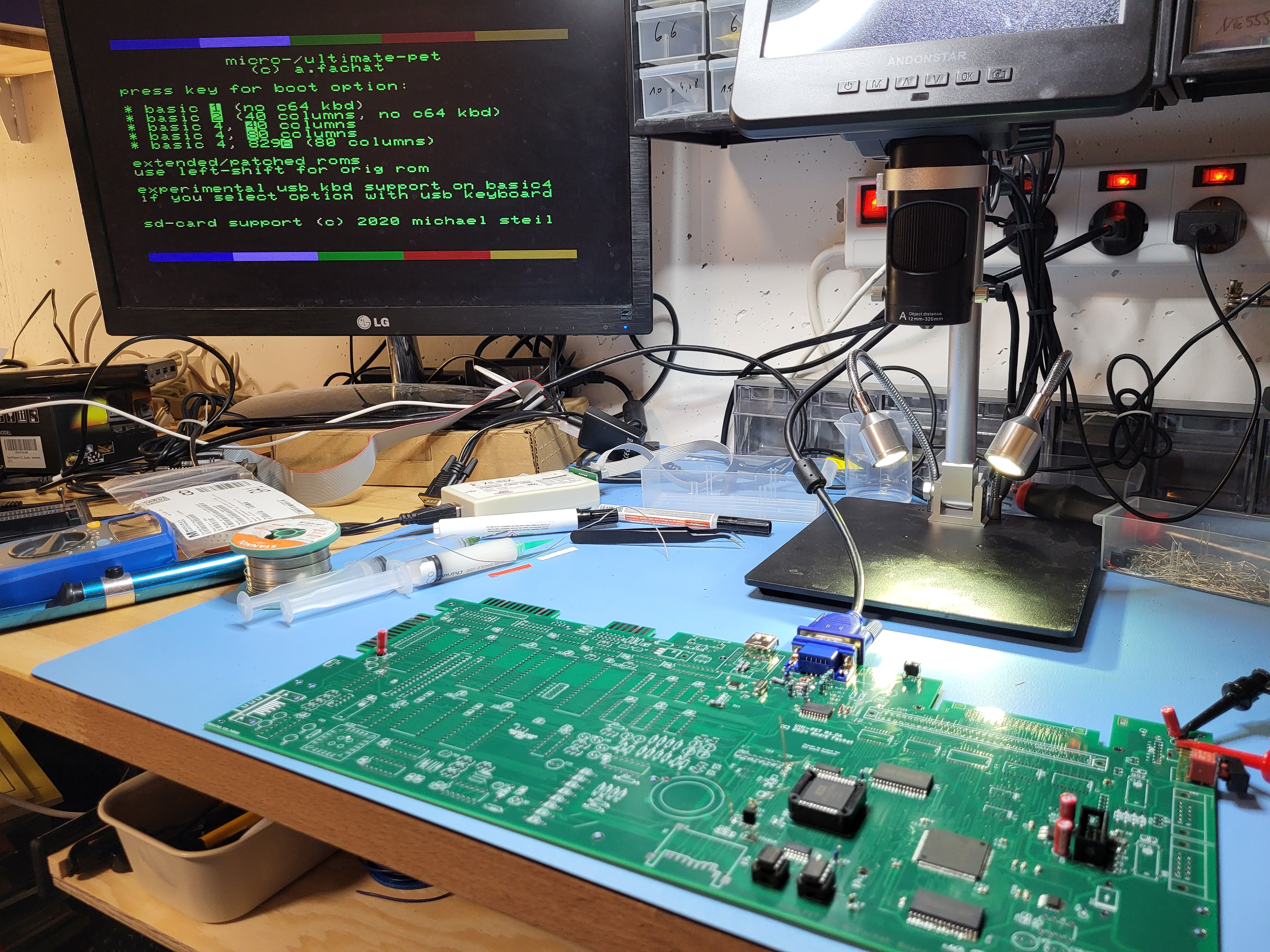
This is a re-incarnation of the Commodore PET computer(s) from the later 1970s.
It is build on a PCB that fits into a C64-II case (with extra cutouts for connectors), and has only parts that can still be obtained new in 2024/2025. A 3D-printed case is also available specific for the Ulti-PET PCB.
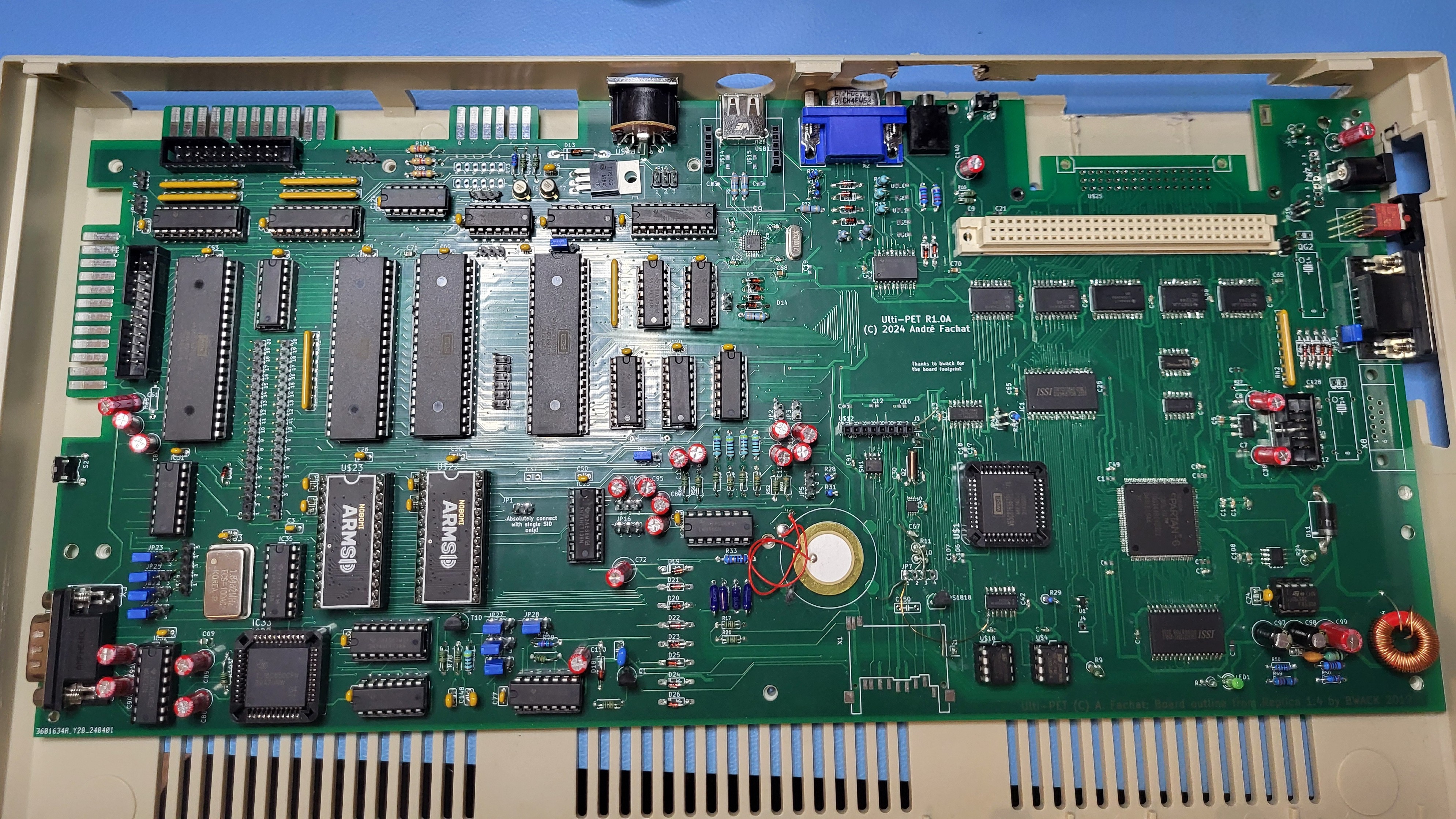
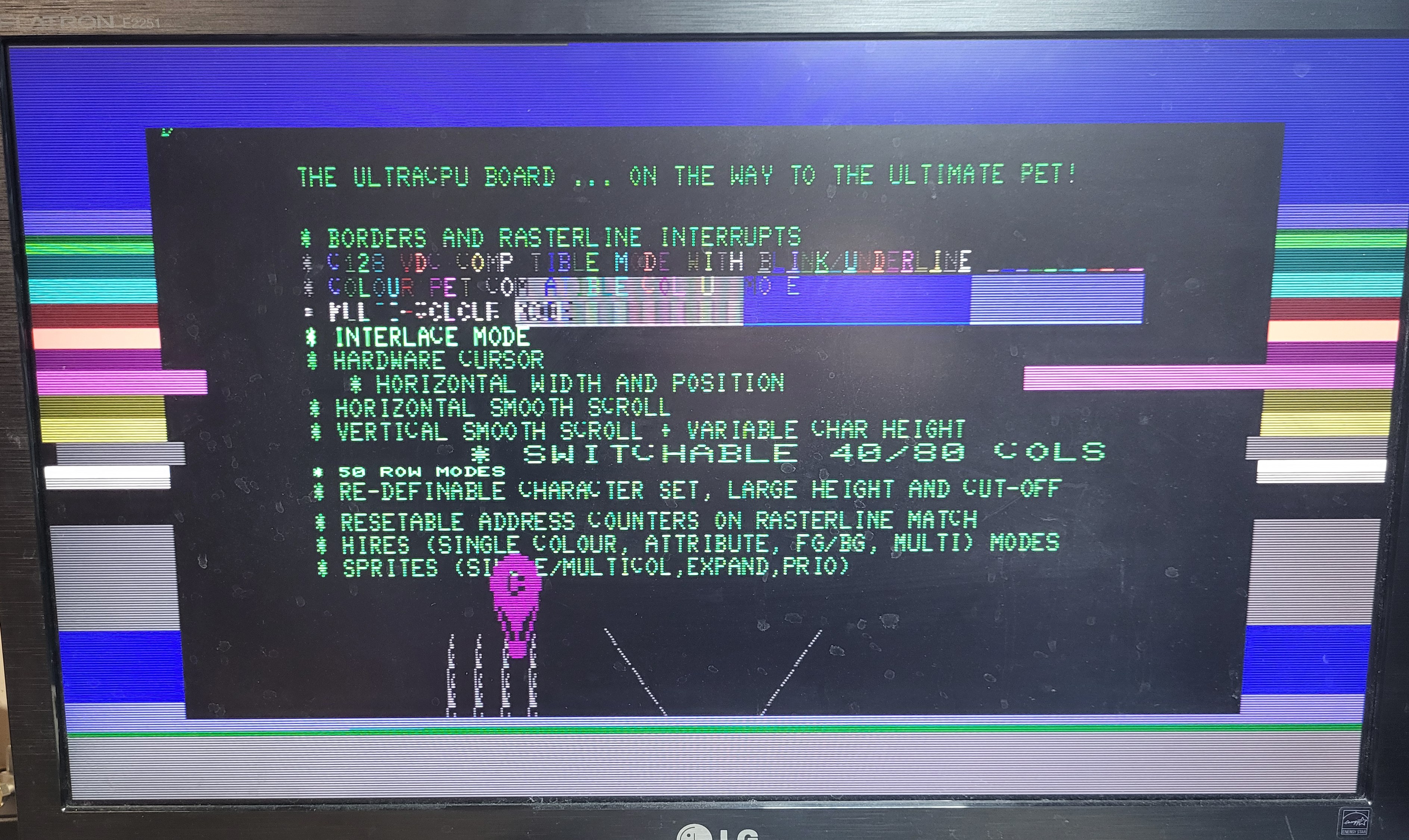
Videos on the machine are coming soon on the YouTube 8-bit times channel.
The board is built with a number of features:
The system architecture is actually rather simple, as you can see in the following graphics.
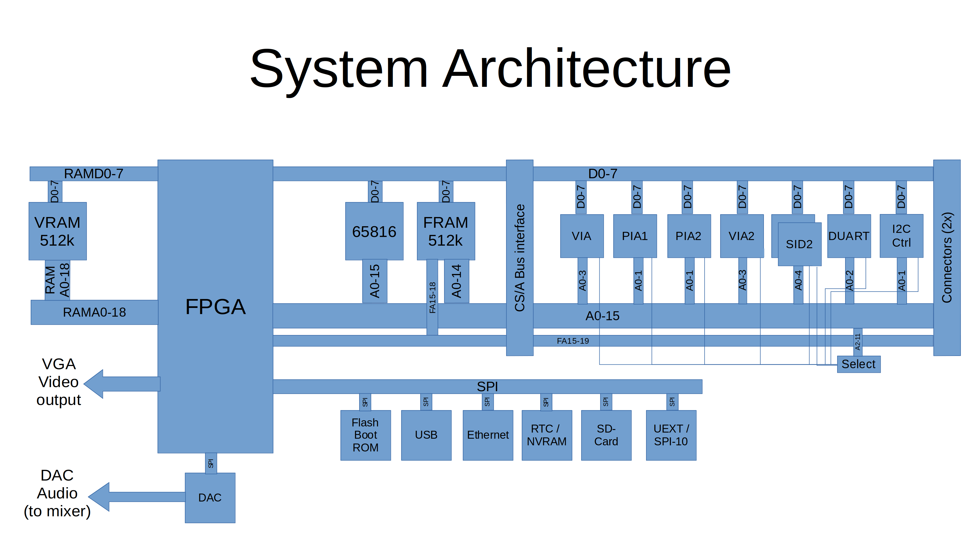
The main functionality is "hidden" inside the FPGA. It does:
On the CPU side of the FPGA it is actually a rather almost normal 65816 computer, with the exception that the bank register (that catches and stores the address lines A16-23 from the CPU's data bus) is in the FPGA, and that there is no ROM. The ROM has been replaced with some code in the FPGA that copies the initial program to the CPU accessible RAM, taking it from the Flash Boot ROM via SPI. This actually simplifies the design, as
The video generation is done using time-sharing access to the video RAM. The VGA output is 720x576 at 50Hz, or 720x480 at 60 Hz. So there is a pixel clock of 27MHz.
The system runs at 13.5MHz, so a byte of pixel output (i.e. eight pixels) has four memory accesses to VRAM. Two of them are reserved for video access, one for fetching the character data (e.g. at $08xxx in the PET), and the second one to fetch the "character ROM" data, i.e. the pixel data for a character. This is also stored in VRAM, and is being loaded there from the Flash Boot ROM by the initial boot loader.
The FPGA reads the character data, stores it to fetch the character pixel data, and streams that out using its internal video shift register.
For more detailled descriptions of the features and how to use them, pls see the FPGA repository that contains the code for the FPGA, as described in the next section.
The Ulti-PET not just has the Ultra-CPU, but also loads of I/O on the one board:
The Ulti-PET includes the standard PET I/O features using the VIA and two PIAs, with some extensions. So, it has:
A Dual UART chip provides two serial interfaces. One interface is a real RS232 with a DB9 connector. The other one is TTL level interface (shared with UEXT, see below).
The USB-C power connector has an USB-to-serial converter, that can be jumpered to the TTL level interface.
An IEC interface is provided using a second VIA chip. Using the VIA shift register, fast mode IEC (like in the C128) is implemented.
Two SID chips are included for your stereo sound pleasure.
The two SID outputs are mixed with the DAC audio output from the Ultra-CPU base. Also, the beeper sound is mixed into the overall sound output.
Two audio amps are included to, so speakers can be directly connected to the board (switched off when the audio jack is used).
When the shift-lock key in the replacement keyboard is defined on a specific position in the keyboard matrix (as is in the keyboard designed by Steve Gray), the key works like a shift-lock key.
In addition, pressing the shift-lock key longer (a few seconds), resets the machine (as long as the keyboard scanning still works).
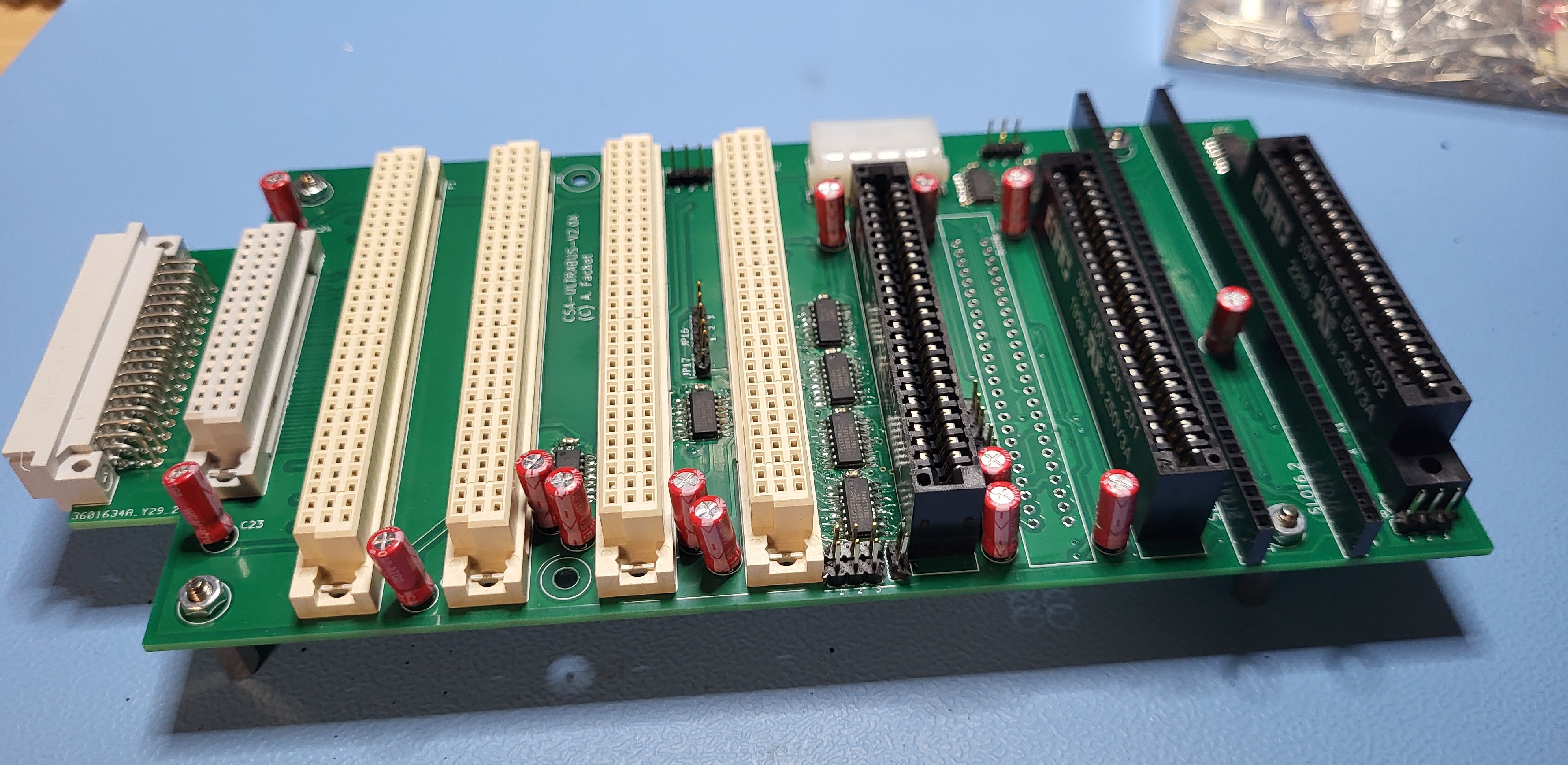
The board has a full width CS/A slot for a single expansion card, plus a short CS/A board for the accompanying CS/A Ultrabus [blocked] Ultra-Bus expansion board. This allows using (compatible) Apple-II, RC2014, and C64 cartridges with the Ulti-PET.
(Older versions up to 1.2a had a problem there that is now fixed!)
The board provides three standard I/O ports:
For the SPI-10 connectors see here. For the UEXT connector see the Olimex UEXT page
Of the modern I/O, currently these are included and supported in the firmware, i.e. in the BASIC4 models:
Note that if you select the boot option while holding the left shift key, a second optional configuration is being used. For more details see the ROM repository, that contains the current version of the firmware and accompanying documentation.
The current revision is 1.3A
The known issues from the 1.2A version have been fixed.
A small number of non-functional issues has been found and documented. See the github list of issues.
1.3a: Update:
1.2a: Update
1.1a: Update:
1.0a: Initial release
Here are the subdirectories:
Note that a case for the Ulti-PET is in the works - the case modifications for the Micro-PET do not work.
In addition, two other repositories are needed - they are separate as they are shared with other variants of the upet-family:
To have the board built, you can use the gerbers that are stored in the zip file in the Board/production subdirectory.
To populate the board, there is an interactive bom (bill of materials) from KiCad, as well as the KiCad BOM CSV export in the bom folder.
Parts numbers can be found in the BOM list. It has parts numbers for Mouser for all parts (except the SID), and for JLCPCB for the SMD parts. You can have JLCPCB assemble most of the SMD parts, and order the rest from Mouser. (Note, to not order parts twice, best remove the JLPCB assembled parts before you upload to Mouser).
The BOM contains an Ethernet breakout board that is put into the connectors "above" the USB port. As an alternative you could use the Wifi breakout board. Note that at this time, this is not tested / programmed yet.
As an audio solution I am planning to use the Visaton K40SQ speakers, if you want to order them as well.
The FPGA is a Xilinx Spartan 6 programmable logic chip. It runs on 1.2V with 3.3V I/O and I programmed it in VHDL.
To build the FPGA content, clone the FPGA repository, and look for the ultipetx.yz.bin, where the x.yz should be replaced with the current board version, or the highest FPGA version below the board version. This needs to be programmed into the SPI flash chip containing the configration for the FPGA.
To actually modify the code, you have to download and install the Xilinx WebISE software and open the ultipetx.yz.xise project file.
To build the boot ROM image, clone the ROM repository, and build the spiimg70m file. This needs to be programmed into the SPI flash ROM containing the 65816 boot code.
The ROM image can be built using gcc, xa65, and make. Use your favourite EPROM programmer to burn it into the SPI Flash chip.
The ROM contains images of all required ROM images for BASIC 1, 2, and 4, and corresponding editor ROMs, including some that have been extended with wedges.
The updated editor ROMs are from Steve's Editor ROM project and can handle C64 keyboards, has a DOS wedge included, and resets into the Micro-PET boot menu. For more details see the description in the ROM repository.
Currently no custom case is publicly available. I just didn't have time to build / test / write up the ones I have on tinkercad. Contact me privately and I can provide you a link.

| Qty | Value | Footprint | References |
|---|---|---|---|
| 45 | 0.1u | cbm_ultipet_v1:C0603 | C11, C12, C100, C101, C102, C103, C104, C105, C106, C107, C108, C109, C110, C111, C112, C113 +29 |
| 30 | 1N4448 | Diode_THT:D_DO-35_SOD27_P7.62mm_Horizontal | D1, D2, D3, D12, D15, D16, D17, D27, D28, D29, D30, D31, D32, D33, D34, D35 +14 |
| 18 | 100n | cbm_ultipet_v1:C025-025X050 | C3, C10, C20, C28, C36, C37, C50, C51, C52, C53, C59, C60, C62, C73, C74, C76 +2 |
| 17 | 100n | cbm_ultipet_v1:C025-024X044 | C84, C92, C124, C131, C132, C133, C134, C135, C137, C138, C139, C141, C142, C143, C144, C145 +1 |
| 15 | JP1E | cbm_ultipet_v1:JP1 | JP1, JP2, JP3, JP4, JP6, JP8, JP9, JP11, JP12, JP15, JP17, JP18, JP22, JP23, JP25 |
| 13 | , , , , , , , , , , , , | ||
| 11 | 1u | cbm_ultipet_v1:C0603 | C1, C4, C14, C49, C54, C55, C56, C57, C120, C121, C123 |
| 10 | 100n | cbm_ultipet_v1:C0603 | C7, C8, C63, C85, C127, C128, C152, C155, C157, C160 |
| 10 | 1u | cbm_ultipet_v1:E2-5 | C86, C87, C90, C91, C95, C96, C115, C116, C117, C118 |
| 10 | 22u | cbm_ultipet_v1:C0805 | C5, C64, C65, C66, C67, C68, C69, C70, C71, C154 |
| 9 | 47u | cbm_ultipet_v1:E2,5-6 | C6, C38, C61, C72, C75, C140, C151, C153, C156 |
| 9 | JP2E | cbm_ultipet_v1:JP2 | JP13, JP14, JP16, JP20, JP24, JP26, JP27, JP28, JP29 |
| 8 | 1N4148DO35-7 | cbm_ultipet_v1:DO35-7 | D19, D20, D21, D22, D23, D24, D25, D26 |
| 7 | ESDBIDIR | cbm_ultipet_v1:SOD323 | UX5, UX6, UX8, UX10, UX11, UX14, UX15 |
| 6 | 470 | cbm_ultipet_v1:0204_7 | R21, R32, R55, R59, R63, R67 |
| 5 | 100u | cbm_ultipet_v1:E2-5 | C9, C21, C98, C129, C136 |
| 5 | 10u | cbm_ultipet_v1:E2-5 | C82, C83, C119, C122, C130 |
| 5 | Conn_01x01_Pin | Connector_PinHeader_2.54mm:PinHeader_1x01_P2.54mm_Vertical | J1, J3, J4, J5, J9 |
| 4 | 100K | cbm_ultipet_v1:0204_7 | R52, R56, R60, R64 |
| 4 | 100k | cbm_ultipet_v1:0204_7 | R54, R58, R62, R66 |
| 4 | 10k | cbm_ultipet_v1:0207_2V | R9, R10, R11, R24 |
| 4 | 10k | cbm_ultipet_v1:0207_10 | R5, R12, R74, R75 |
| 4 | 18p | cbm_ultipet_v1:C0603 | C29, C30, C39, C40 |
| 4 | 1k | cbm_ultipet_v1:0204V | R18, R19, R20, R37 |
| 4 | 2200 | cbm_ultipet_v1:C025-025X050 | C161, C162, C163, C164 |
| 4 | 22000 | cbm_ultipet_v1:C025-025X050 | C78, C79, C80, C81 |
| 4 | 220k | cbm_ultipet_v1:0204_7 | R53, R57, R61, R65 |
| 4 | 74138N | Package_DIP:DIP-16_W7.62mm_Socket_LongPads | IC9, IC11, IC28, IC35 |
| 3 | 0.1u | Capacitor_SMD:C_0603_1608Metric | C165, C166, C167 |
| 3 | 100 | cbm_ultipet_v1:0207_2V | R26, R39, R40 |
| 3 | 100k | cbm_ultipet_v1:0207_7 | R77, R79, R80 |
| 3 | 10k | Resistor_SMD:R_0805_2012Metric_Pad1.20x1.40mm_HandSolder | R30, R47, R48 |
| 3 | 1N4148 | cbm_ultipet_v1:D-5 | D5, D6, D8 |
| 3 | 1k | cbm_ultipet_v1:0207_10 | R45, R46, R73 |
| 3 | 33 | cbm_ultipet_v1:0204_7 | R1, R2, R4 |
| 3 | 470 | cbm_ultipet_v1:0204V | R13, R14, R15 |
| 3 | 74245DW | Package_SO:SOP-20_7.5x12.8mm_P1.27mm | IC2, IC4, IC5 |
| 3 | Conn_01x09 | Connector_PinHeader_2.54mm:PinHeader_1x09_P2.54mm_Vertical | J10, J11, J12 |
| 2 | 0.01u | cbm_ultipet_v1:C025-024X044 | C148, C149 |
| 2 | 100 | cbm_ultipet_v1:0204V | R28, R31 |
| 2 | 100u | Capacitor_THT:CP_Radial_D5.0mm_P2.00mm | C158, C159 |
| 2 | 10k | cbm_ultipet_v1:RN-9 | RN1, RN2 |
| 2 | 10k | Resistor_THT:R_Axial_DIN0204_L3.6mm_D1.6mm_P2.54mm_Vertical | R34, R35 |
| 2 | 10k | cbm_ultipet_v1:0204_5 | R6, R16 |
| 2 | 2T2222 | cbm_ultipet_v1:TO92 | T6, T7 |
| 2 | 2k2 | cbm_ultipet_v1:0204V | R23, R36 |
| 2 | 2k4 | cbm_ultipet_v1:RN-9 | RN3, RN5 |
| 2 | 31-XX | cbm_ultipet_v1:B3F-31XX | S1, S2 |
| 2 | 390 | cbm_ultipet_v1:0207_2V | R17, R22 |
| 2 | 4k7 | cbm_ultipet_v1:0204_7 | R3, R27 |
| 2 | 4k7 | cbm_ultipet_v1:0207_10 | R43, R44 |
| 2 | 4u7 | cbm_ultipet_v1:E2,5-6 | C88, C89 |
| 2 | 512k x8 10ns SRAM | Package_SO:TSOP-II-44_10.16x18.41mm_P0.8mm | IC1, IC10 |
| 2 | 5k1 | cbm_ultipet_v1:RN-9 | RN4, RN6 |
| 2 | 5k1 | cbm_ultipet_v1:0207_2V | R41, R42 |
| 2 | 68 | cbm_ultipet_v1:0204V | R7, R8 |
| 2 | 74244DW | Package_SO:SOP-20_7.5x12.8mm_P1.27mm | IC13, IC19 |
| 2 | 7474N | Package_DIP:DIP-14_W7.62mm_Socket_LongPads | IC27, IC40 |
| 2 | 74LS641 | Package_DIP:DIP-20_W7.62mm_Socket_LongPads | UX20, UX21 |
| 2 | CBMTAPE | cbm_ultipet_v1:JP6 | P6, P7 |
| 2 | CD4053B | Package_SO:SOIC-16_3.9x9.9mm_P1.27mm | U4, U5 |
| 2 | LDI1117 | cbm_ultipet_v1:SOT223 | UX3, UX17 |
| 2 | LM386 | Package_DIP:DIP-8_W7.62mm_Socket_LongPads | U6, U7 |
| 2 | M09-182 | Connector_Dsub:DSUB-9_Pins_Horizontal_P2.77x2.84mm_EdgePinOffset9.90mm_Housed_MountingHolesOffset11.32mm | X7, X8 |
| 2 | MAX232 | Package_DIP:DIP-16_W7.62mm_Socket_LongPads | IC31, IC32 |
| 2 | PIA | Package_DIP:DIP-40_W15.24mm_Socket_LongPads | IC17, IC20 |
| 2 | SID | Package_DIP:DIP-28_W15.24mm_Socket_LongPads | UX22, UX23 |
| 2 | SPIFLASH | Package_DIP:DIP-8_W7.62mm_Socket_LongPads | UX4, UX18 |
| 2 | SolderJumper_3_Bridged12 | Jumper:SolderJumper-3_P1.3mm_Bridged12_RoundedPad1.0x1.5mm_NumberLabels | JP5, JP21 |
| 2 | VIA | Package_DIP:DIP-40_W15.24mm_Socket_LongPads | IC15, IC36 |
| 2 | ~ | Connector_IDC:IDC-Header_2x05_P2.54mm_Vertical | P4, P9 |
| 1 | 0.01, 50V | cbm_ultipet_v1:C025-024X044 | C125 |
| 1 | 0.22 | cbm_ultipet_v1:0204_7 | R49 |
| 1 | 0.47 | cbm_ultipet_v1:C025-025X050 | C126 |
| 1 | 1,8432MHz | cbm_ultipet_v1:SG51 | QG3 |
| 1 | 1.0u Cer | cbm_ultipet_v1:C0603 | C24 |
| 1 | 10 | cbm_ultipet_v1:0207_10 | R33 |
| 1 | 10k | cbm_ultipet_v1:RN-8 | RN8 |
| 1 | 10k | cbm_ultipet_v1:0207_7 | R78 |
| 1 | 12MHz | cbm_ultipet_v1:HC49_S | Q3 |
The 378 most common of 466 parts.
fachat/cbm_ultipet
Note: this is a part of a larger set of repositories, with upetfamily as the main repository.

fachat/cbm_ultipet
Note: this is a part of a larger set of repositories, with upetfamily as the main repository.


agkaminski/ZAK181
Improved ZAK180: DIY all-in-keyboard computer featuring Z180 and floppy drive.


CPTforever/8088-MicroATX-Computer
A 8088 based, IBM 5150 like computer compatible with the MicroATX motherboard form factor.

siliconvalleyar-oss/kicad_preview
KiCad Preview - Flutter viewer for KiCad schematics and PCBs

lynchaj/duodyne
Duodyne is a hobbyist retrocomputer system designed to run ROMWBW. It is comprised of modules on a system bus

It measures 389.8 × 179.5 mm and has 4 copper layers, 1.6 mm thick.
466 parts, built around the MAX232N, LM386, CD4053BE and LDI1117-3.3H. The full list of its parts is on this page, with links to each part's symbol and footprint where PCBKit's library has them.
From the fachat/cbm_ultipet repository on GitHub, at the commit this page was made from: the board is Board/cbm_ultipet_v1.kicad_pcb and its schematic Board/A%2fV.kicad_sch. PCBKit opens the board in the browser, with nothing to install.
Its repository publishes it under the GPL-3.0 licence: you may reuse it on that licence's terms (keep the author's notice, and for a copyleft licence share your changes alike).