
4 layers170.2 × 170.2 mm
Motherboard
MicroLind-Developers/microlind-hw
Hardware repository for the microlind project
149 partsCERN-OHL-P-2.0

 fachat/cbm_keyboard7
Keyboard replacement solutions for the Commodore PET
Petkn is an open-source printed circuit board by fachat, from the fachat/cbm_keyboard repository on GitHub. It is a 2-layer board of 386.1 × 102 mm with 227 parts on 270 nets, routed with 6,575 tracks and 769 vias.
It is built around the ATMEGA32A-AU, 74LS174DC and 74HCT00D, with the 74HCT85D among its other parts. Its parts include 81 diodes, 64 switches, 33 capacitors, 7 ICs and 5 resistors. It belongs with the AVR (ATmega, ATtiny) boards of this library.


Note: this is a part of a larger set of repositories, with upet_family as the main repository.
This is part of a re-incarnation of the Commodore PET computer(s) from the later 1970s.
This repo shows how to build a keyboard for the Commodore PET, mainly for my own re-incarnation, but potentially for original PET as well (untested).
Keyboards can be seen in the PETindex keyboard section.
This keyboard is the typewriter-stlye keyboard used in most 40 column models, except for the originals with the chicklet keyboard.
For my builds I started by using the N-type keyboard PCB by Steve Gray from his MX replacement keyboards projects As Steve only has the PCB, I designed a 3D-printable base support for the PCB. It is available on tinkercad and the STL files are also available here.
Based on that I created a new R3 version of the board that includes options for backlit LEDs and keyboard controllers allowing key re-mapping independent from the PET's own editor ROM. You can find it in PET-N
NOTE: In R3.0A you need to fix some things:
In the current R3.0B these two fixes have been applied, but the actual PCB is not tested yet (and probably never will). A future 3.1 fix this for good.
The R3 PCB has (optionally) two Atmega32a microcontrollers on board, that implement two functions:
To program the Microcontrollers you need an AVR programming tool like the AVRisp MkII that I use, or similar, that can program via the SPI interface (plus Reset) on the 6 pin programming header (which exists separately for each of the two Microcontrollers)
Both microcontrollers are connected to the I2C bus on the extended UPET keyboard interface.
Currently the keyboard controller maps the keys 1:1 from the keyboard matrix to the host keyboard interface.
In addition it sends the pressed keys (hardware key index) via I2C to address 0x10 (which is the LED controller).
Also, the keyboard mapping has these options:
Note that in the future more mappings may be implemented.
Selection of the mapping is done by pressing the SRQ key a few seconds long. The keyboard will then send a menu text to the host that instructs the user how to switch the mapping. It is best if the menu is triggered e.g. on the BASIC prompt.
The mapping is stored in the Atmega's EEPROM, and thus retained when the machine is switched off.
The LED controller listens on the I2C address 0x10 for commands.
With these commands you can set the constant value of each key LED, but also trigger certain programs that involve either a single key, or multiple keys. For single keys you can let the colour slowly get dimmer until the LED is off, and then optionally restart with the original value.
The DILUTE program tries to do a simulated flow of the colour from the given key to the surrounding keys. It is not as good and smooth as it could be as the Atmega lacks memory to store the required precision of colour values.
The LOGO just sends the logo onto the keypad, and then lets it decay.
        // single LED programs. Followed by index, three colours, and a parameter
        LP_CONST        = 0,    // constant value, using the three parameters as RGB
        LP_LINDECAY     = 1,    // linear decay (note may change hue while getting lower)
        LP_LINDECAYLOOP = 2,    // linear decay with restart

        // single command program
        SP_KEYPRESS     = 64,   // just followed by the index to indicate a pressed key

        // multi-key programs
        KP_DILUTE       = 128,  // set initial value to given params, then let it flow off
        KP_LOGO         = 129,  // C= logo on the keypad
All commands except KEYPRESS expect the key index, three colours, and a parameter after the command, i.e. six bytes in total. KEYPRESS only has the index and thus requires only two bytes.
The PCB needs some kind of support to be mounted into the PET or the Ulti-/Micro-PET cases. There are two versions for Steve's and my derived PCB, the first one for the extended that caters for the different connector, and the one better suitable for the original PCB.
This is the PET N-type keyboard available from Texelec.
As this is the PCB only, I have created a support structure for this too. Note, however, as I now prefer Steve's PCB, I only have an old version of the supports on tinkercad.
Two of each of these supports make up a keyboard base plate, where you only need to clip in the PCB for the keyboard with the mounted key switches. Then they have about the same dimensions as a C64 keyboard, and you can use them on top of the C64 keyboard support stands.
There are two options, either use standard key caps, or 3D-printed ones.
As, for the self-built keyboards from option 1 or 2 some standard MX switches are used, standard key caps can be used as well. There is one caveat, however.
Newer key caps typically have a different inclination for each row of keys, that is the angle of the top key surface against the horizontal is different for each row. This is to facilitate easier typing. In fact even the C64 keyboard has this. The old PET keyboards, however, have the same angle - which is not zero! - for all rows. This makes it easier to use the same cap (in terms of physical dimensions) on all rows, and just print on a different character for each key. Read more on those key profiles.
I used two type of standard key caps:
XDA profile, unmarked: this set of key caps does not have a print on it, and all keys have the same angle - zero. So it is possible to use any of the key caps in any row. Which is important, as you need a specific number of keys for each key width. Also, this set has space bars in different lengths, and there is one that fits the 6.25 character wide space bar for the petskey and sjg keyboards. For the markings I just used a pen...
This one Glorious PC Gaming Race ABS Doubleshot black, ANSI layout GAKC-045 I actually bought more or less by accident. I only noticed that it has different angles per row when I tried it out. However, with the amount of caps I was able to only use a wrong angle on Shift Lock, left Shift, Return and "4" - but it's barely noticable. For the markings I used template from Steve's page, printed it on sticky paper, cut it out and glued it on the keys where the original did not fit.
As a third option I used 3-D printed key caps that I designed myself.
The keycaps are made of three parts each:
I created all parts, and integrated them in the Tinkercad web tool.
The key form is created using OpenSCAD by a parametric generator (by Thingieverse user rsheldiii, published under the CC BY-SA 3.0 license). Here is the parameter file. Only the key width needs to be adapted, and the inversion of the top for the space key.
Most of the top character prints are made from a Microgramm font, converted to SVG using the Font Squirrel web page.
Some top characters, and especially the top words ("SHIFT", "RUN STOP" etc) are taken from Steve's github page. As SVG exported from inkscape did not work when imported into tinkercad, I had to make screenshots from each character, and convert these screenshots into SVGs using this online converter.
The front characters are all from an SVG file from wikipedia, from which I also took screenshots and converted to SVG as above.
You can find an oder version of the the STL files here, in four parts due to its size. The current version is linked from tinkercad below. Please note that it took me about 100+ hours just to print the full set of keys on my Snapmaker printer in high quality. After printing you have to remove the supports that anchor the stem to the outside of the keycaps so it does not break away when printing.
For your convenience there is an open project at PCBWay to print the key caps, see the links.
The PCBs work with standard Cherry-type/-compatible switches. I only tested Cherry brand switches, though. You may select depending on your preference regarding force needed, click noise etc.
I found the MX1A-C1NW a good compromise for me.
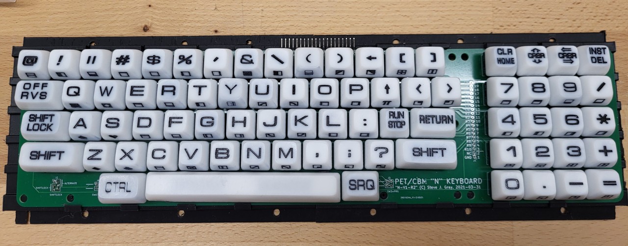 Assembled keyboard with white resin printed caps, with key prints painted with black alcohol ink
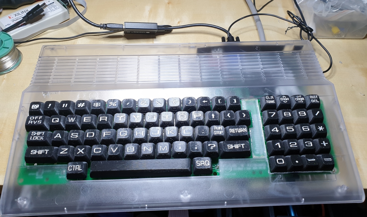 Assembled keyboard with black PLA printed caps, with key prints painted with white alcohol ink
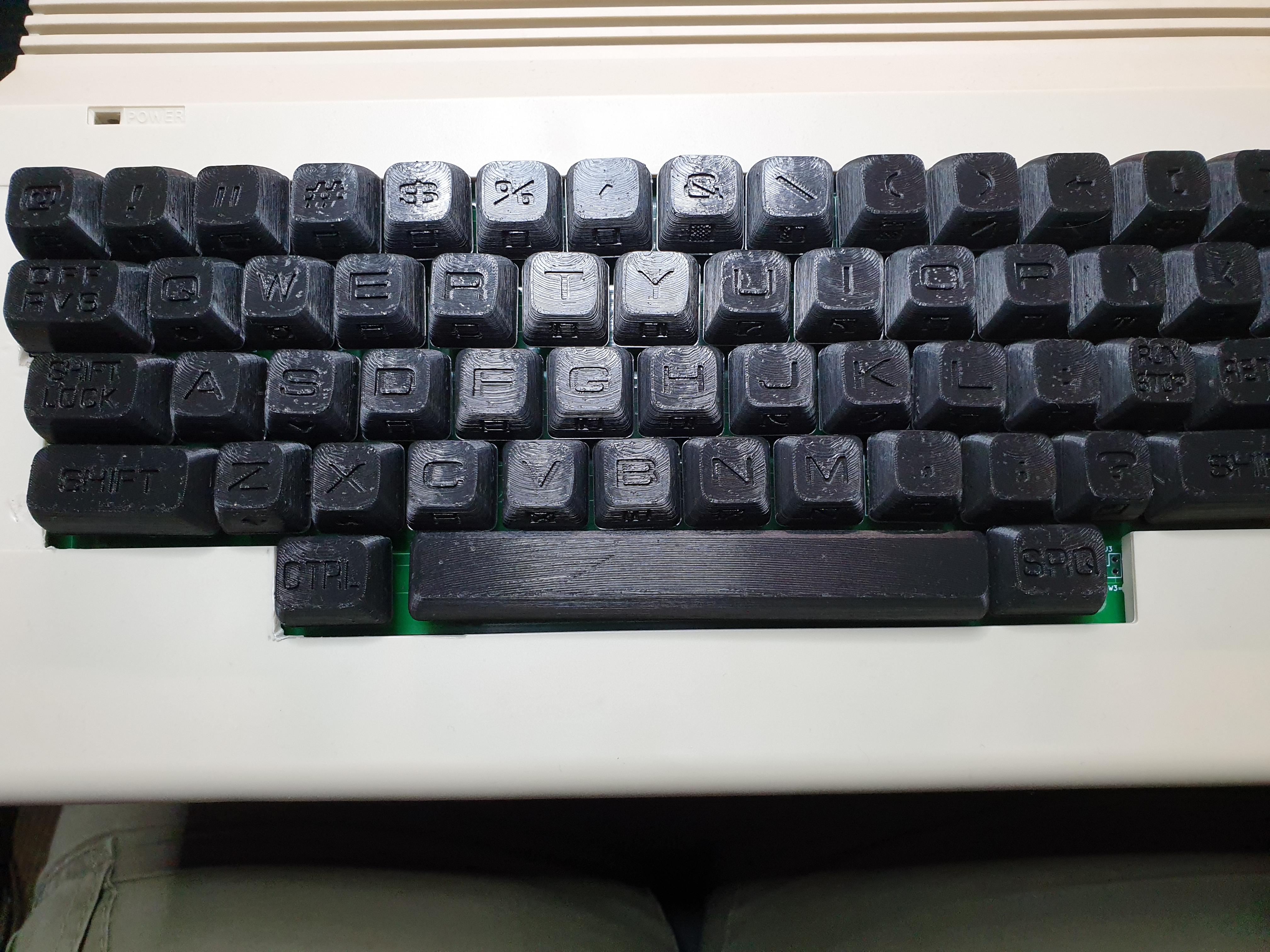 Assembled keyboard with black PLA printed caps
| Qty | Value | Footprint | References |
|---|---|---|---|
| 81 | 1N4448 | Diode_SMD:D_SOD-323_HandSoldering | D1, D2, D10, D11, D12, D13, D14, D15, D16, D17, D18, D19, D20, D21, D22, D23 +65 |
| 22 | 100u | Capacitor_SMD:C_1206_3216Metric_Pad1.33x1.80mm_HandSolder | C1, C2, C15, C16, C18, C19, C20, C21, C22, C23, C24, C25, C26, C27, C28, C29 +6 |
| 14 | SolderJumper_2_Bridged | Jumper:SolderJumper-2_P1.3mm_Open_RoundedPad1.0x1.5mm | JC1, JC2, JC3, JC4, JC5, JC6, JC7, JC8, JP1, JP2, JP3, JP5, JP8, JP11 |
| 11 | 100n | Capacitor_SMD:C_0805_2012Metric_Pad1.18x1.45mm_HandSolder | C7, C8, C9, C10, C11, C12, C13, C14, C17, C30, C31 |
| 3 | 10k | Resistor_SMD:R_0603_1608Metric | R3, R4, R5 |
| 3 | SolderJumper_3_Bridged12 | Jumper:SolderJumper-3_P1.3mm_Bridged12_RoundedPad1.0x1.5mm_NumberLabels | JP4, JP6, JP7 |
| 2 | 2k2 | Resistor_SMD:R_0603_1608Metric | R1, R2 |
| 2 | 74LS174 | Package_SO:SO-16_3.9x9.9mm_P1.27mm | U4, U6 |
| 2 | ATmega32A-A | Package_QFP:TQFP-44_10x10mm_P0.8mm | U2, U8 |
| 2 | AVR-ISP-6 | Connector_IDC:IDC-Header_2x03_P2.54mm_Vertical | J4, J7 |
| 2 | SolderJumper_2_Bridged | Jumper:SolderJumper-2_P1.3mm_Bridged_RoundedPad1.0x1.5mm | JP9, JP10 |
| 1 | "!" | petkn:SW_Cherry_MX_1.00u_PCB_with_RGB_LED | SW80 |
| 1 | "#" | petkn:SW_Cherry_MX_1.00u_PCB_with_RGB_LED | SW79 |
| 1 | "$" | petkn:SW_Cherry_MX_1.00u_PCB_with_RGB_LED | SW71 |
| 1 | "%" | petkn:SW_Cherry_MX_1.00u_PCB_with_RGB_LED | SW78 |
| 1 | "&" | petkn:SW_Cherry_MX_1.00u_PCB_with_RGB_LED | SW77 |
| 1 | "'" | petkn:SW_Cherry_MX_1.00u_PCB_with_RGB_LED | SW70 |
| 1 | "(" | petkn:SW_Cherry_MX_1.00u_PCB_with_RGB_LED | SW76 |
| 1 | ")" | petkn:SW_Cherry_MX_1.00u_PCB_with_RGB_LED | SW68 |
| 1 | "," | petkn:SW_Cherry_MX_1.00u_PCB_with_RGB_LED | SW21 |
| 1 | ":" | petkn:SW_Cherry_MX_1.00u_PCB_with_RGB_LED | SW36 |
| 1 | ";" | petkn:SW_Cherry_MX_1.00u_PCB_with_RGB_LED | SW28 |
| 1 | "<" | petkn:SW_Cherry_MX_1.00u_PCB_with_RGB_LED | SW5 |
| 1 | ">" | petkn:SW_Cherry_MX_1.00u_PCB_with_RGB_LED | SW12 |
| 1 | "?" | petkn:SW_Cherry_MX_1.00u_PCB_with_RGB_LED | SW20 |
| 1 | "@" | petkn:SW_Cherry_MX_1.00u_PCB_with_RGB_LED | SW15 |
| 1 | "A" | petkn:SW_Cherry_MX_1.00u_PCB_with_RGB_LED | SW48 |
| 1 | "B" | petkn:SW_Cherry_MX_1.00u_PCB_with_RGB_LED | SW30 |
| 1 | "C" | petkn:SW_Cherry_MX_1.00u_PCB_with_RGB_LED | SW31 |
| 1 | "D" | petkn:SW_Cherry_MX_1.00u_PCB_with_RGB_LED | SW47 |
| 1 | "E" | petkn:SW_Cherry_MX_1.00u_PCB_with_RGB_LED | SW63 |
| 1 | "F" | petkn:SW_Cherry_MX_1.00u_PCB_with_RGB_LED | SW39 |
| 1 | "G" | petkn:SW_Cherry_MX_1.00u_PCB_with_RGB_LED | SW46 |
| 1 | "H" | petkn:SW_Cherry_MX_1.00u_PCB_with_RGB_LED | SW38 |
| 1 | "I" | petkn:SW_Cherry_MX_1.00u_PCB_with_RGB_LED | SW53 |
| 1 | "J" | petkn:SW_Cherry_MX_1.00u_PCB_with_RGB_LED | SW45 |
| 1 | "K" | petkn:SW_Cherry_MX_1.00u_PCB_with_RGB_LED | SW37 |
| 1 | "L" | petkn:SW_Cherry_MX_1.00u_PCB_with_RGB_LED | SW44 |
| 1 | "M" | petkn:SW_Cherry_MX_1.00u_PCB_with_RGB_LED | SW29 |
| 1 | "N" | petkn:SW_Cherry_MX_1.00u_PCB_with_RGB_LED | SW22 |
| 1 | "O" | petkn:SW_Cherry_MX_1.00u_PCB_with_RGB_LED | SW60 |
| 1 | "P" | petkn:SW_Cherry_MX_1.00u_PCB_with_RGB_LED | SW52 |
| 1 | "Q" | petkn:SW_Cherry_MX_1.00u_PCB_with_RGB_LED | SW64 |
| 1 | "R" | petkn:SW_Cherry_MX_1.00u_PCB_with_RGB_LED | SW55 |
| 1 | "S" | petkn:SW_Cherry_MX_1.00u_PCB_with_RGB_LED | SW40 |
| 1 | "T" | petkn:SW_Cherry_MX_1.00u_PCB_with_RGB_LED | SW62 |
| 1 | "U" | petkn:SW_Cherry_MX_1.00u_PCB_with_RGB_LED | SW61 |
| 1 | "V" | petkn:SW_Cherry_MX_1.00u_PCB_with_RGB_LED | SW23 |
| 1 | "W" | petkn:SW_Cherry_MX_1.00u_PCB_with_RGB_LED | SW56 |
| 1 | "X" | petkn:SW_Cherry_MX_1.00u_PCB_with_RGB_LED | SW24 |
| 1 | "Y" | petkn:SW_Cherry_MX_1.00u_PCB_with_RGB_LED | SW54 |
| 1 | "Z" | petkn:SW_Cherry_MX_1.00u_PCB_with_RGB_LED | SW32 |
| 1 | "[" | petkn:SW_Cherry_MX_1.00u_PCB_with_RGB_LED | SW7 |
| 1 | "\" | petkn:SW_Cherry_MX_1.00u_PCB_with_RGB_LED | SW69 |
| 1 | "]" | petkn:SW_Cherry_MX_1.00u_PCB_with_RGB_LED | SW14 |
| 1 | 74HCT00 | Package_SO:SOIC-14_3.9x8.7mm_P1.27mm | U9 |
| 1 | 74HCT85 | Package_SO:SO-16_3.9x9.9mm_P1.27mm | U3 |
| 1 | 74LS145 | Package_SO:SO-16_3.9x9.9mm_P1.27mm | U7 |
| 1 | ASE-xxxMHz | Oscillator:Oscillator_SMD_Abracon_ASE-4Pin_3.2x2.5mm | Y1 |
| 1 | B ARROW | petkn:SW_Cherry_MX_1.00u_PCB_with_RGB_LED | SW75 |
| 1 | CLR/HOME | petkn:SW_Cherry_MX_1.00u_PCB_with_RGB_LED | SW74 |
| 1 | Extended_PET_keyboard_connector | petkn:PET_Extended_Keyboard_Connector | J1 |
| 1 | INS/DEL | petkn:SW_Cherry_MX_1.00u_PCB_with_RGB_LED | SW65 |
| 1 | KP "*" | petkn:SW_Cherry_MX_1.00u_PCB_with_RGB_LED | SW33 |
| 1 | KP "+" | petkn:SW_Cherry_MX_1.00u_PCB_with_RGB_LED | SW17 |
| 1 | KP "-" | petkn:SW_Cherry_MX_1.00u_PCB_with_RGB_LED | SW9 |
| 1 | KP "." | petkn:SW_Cherry_MX_1.00u_PCB_with_RGB_LED | SW2 |
| 1 | KP "/" | petkn:SW_Cherry_MX_1.00u_PCB_with_RGB_LED | SW49 |
| 1 | KP "0" | petkn:SW_Cherry_MX_1.00u_PCB_with_RGB_LED | SW10 |
| 1 | KP "1" | petkn:SW_Cherry_MX_1.00u_PCB_with_RGB_LED | SW26 |
| 1 | KP "2" | petkn:SW_Cherry_MX_1.00u_PCB_with_RGB_LED | SW18 |
| 1 | KP "3" | petkn:SW_Cherry_MX_1.00u_PCB_with_RGB_LED | SW25 |
| 1 | KP "4" | petkn:SW_Cherry_MX_1.00u_PCB_with_RGB_LED | SW42 |
| 1 | KP "5" | petkn:SW_Cherry_MX_1.00u_PCB_with_RGB_LED | SW34 |
| 1 | KP "6" | petkn:SW_Cherry_MX_1.00u_PCB_with_RGB_LED | SW41 |
| 1 | KP "7" | petkn:SW_Cherry_MX_1.00u_PCB_with_RGB_LED | SW58 |
| 1 | KP "8" | petkn:SW_Cherry_MX_1.00u_PCB_with_RGB_LED | SW50 |
| 1 | KP "9" | petkn:SW_Cherry_MX_1.00u_PCB_with_RGB_LED | SW57 |
| 1 | KP "=" | petkn:SW_Cherry_MX_1.00u_PCB_with_RGB_LED | SW1 |
| 1 | L SHIFT | petkn:SW_Cherry_MX_2.00u_PCB_with_RGB_LED | SW16 |
The 213 most common of 227 parts.
It measures 386.1 × 102 mm and has 2 copper layers, 1.6 mm thick.
227 parts, built around the ATMEGA32A-AU, 74LS174DC, 74HCT00D and 74HCT85D. The full list of its parts is on this page, with links to each part's symbol and footprint where PCBKit's library has them.
From the fachat/cbm_keyboard repository on GitHub, at the commit this page was made from: the board is PET-N/petkn.kicad_pcb and its schematic PET-N/connector.kicad_sch. PCBKit opens the board in the browser, with nothing to install.
Its repository states no licence, so its author keeps all rights: ask fachat before reusing the design.
MicroLind-Developers/microlind-hw
Hardware repository for the microlind project

telec16/modular-synth
Little side project, don't expect much updates.


dmogn/plc_controller_mega32l_pcb_scheme
PLC controller hardware PCB scheme. ATMega32L, RS485 industrial bus interface, 8 ADC inputs, 8 PWM out, 6 GPIO

promesoft/KicadJE_uP_DAC
STM32 and ATMEGA32A - Eurorack DAC MCP4822 output - Use for Sub 400Hz DDS, LFO, ADSR, Effects - and a small 555 VCO - DDS1 DDS2

RichardRozehnal/Atari-SIO2SD-Igi-Version
SIO2SD disk drive emulator for 8bit Atari.

promesoft/KicadJE_ADSR_Mega32
Envelope for ATMEGA32A - Formant VCO - PT2399 Reverb