2 layers181.1 × 95.9 mm
Combined branches
TJREVERB/reverb_interface
Interface board rework, moved from Eagle to Kicad
140 parts
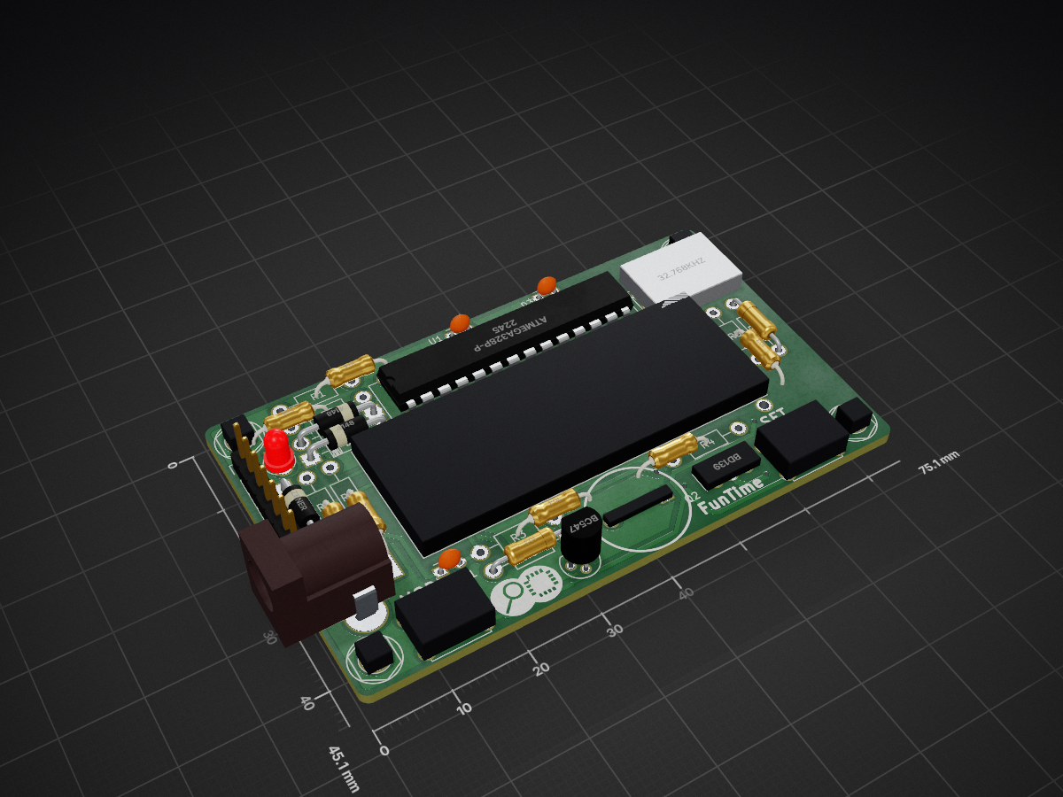
 ExploreEmbedded/FunTime
A DIY wall clock that doubles up as automatic night lamp
Explore Clock is an open-source printed circuit board by ExploreEmbedded, from the ExploreEmbedded/FunTime repository on GitHub. It is a 2-layer board of 75.1 × 45.1 mm with 34 parts on 37 nets, routed with 581 tracks and 34 vias.
It is built around the ATMEGA328P-PU, BC547 and BD139, with the CR2032弯脚电池片铜 3V among its other parts. Its parts include 9 resistors, 8 connectors, 5 diodes, 2 ICs and 2 transistors. It belongs with the lEDs and displays boards and the AVR (ATmega, ATtiny) boards of this library.


FunTime is a simple DIY clock kit, that doubles up as automatic night lamp. While building this kit we learn about how time is computed, converted to secs, mins, hours, days and eventually into years! We will also learn about measuring light and controlling a LED depending on time and light. The end goal is build a cool wall clock, use the time and the light intensity to turn on the night lamp. It will take about an hour to solder and assemble the kit.
Get one at: https://www.exploreembedded.com/product/funTime
Acrylic Design


| Qty | Value | Footprint | References |
|---|---|---|---|
| 4 | CONN_01X01 | EE:M3_mounting | P2, P3, P4, P5 |
| 3 | 10K | Resistors_ThroughHole:Resistor_Horizontal_RM10mm | R2, R5, R8 |
| 2 | 100K | Resistors_ThroughHole:Resistor_Horizontal_RM10mm | R1, R3 |
| 2 | 1K | Resistors_ThroughHole:Resistor_Horizontal_RM10mm | R6, R7 |
| 2 | 4148 | Diodes_ThroughHole:Diode_DO-41_SOD81_Horizontal_RM10 | D4, D5 |
| 2 | CONN_01X01 | EE:Logo_8 | P14, P14 |
| 2 | SW_PUSH | EE:SW_PUSH_SMALL | SW1, SW2 |
| 1 | 0.1uF | Capacitors_ThroughHole:C_Disc_D3_P2.5 | C1 |
| 1 | 0.5 W Straw Hat LED | Capacitors_ThroughHole:C_Disc_D3_P2.5 | D3 |
| 1 | 32.768KHz | EE:RTC_Crystal | Y1 |
| 1 | 470E | Resistors_ThroughHole:Resistor_Horizontal_RM10mm | R4 |
| 1 | 47E | Resistors_ThroughHole:Resistor_Horizontal_RM10mm | R9 |
| 1 | ATMEGA328P-P | Housings_DIP:DIP-28_W7.62mm | IC1 |
| 1 | BARREL_JACK | EE:JACK_ALIM | CON1 |
| 1 | BC547 | TO_SOT_Packages_THT:TO-92_Molded_Narrow | Q1 |
| 1 | BD139 | TO_SOT_Packages_THT:SOT126_SOT32_Housing_Vertical_BigPads | Q2 |
| 1 | Buzzer | EE:BUZ3-5 | SP1 |
| 1 | CA56-12 | Displays_7-Segment:Cx56-12 | AFF1 |
| 1 | CONN_01X07 | Pin_Headers:Pin_Header_Straight_1x07 | P1 |
| 1 | CR-2032 | EE:BATT_rtc_XL | BT1 |
| 1 | LDR | Capacitors_ThroughHole:C_Disc_D3_P2.5 | U1 |
| 1 | LOGO | warning Logo:Logo_silk_warning_5x4.2mm | G*** |
| 1 | PLED | LEDs:LED-3MM | D2 |
| 1 | ZENER | Diodes_ThroughHole:Diode_DO-41_SOD81_Horizontal_RM10 | D1 |
It measures 75.1 × 45.1 mm and has 2 copper layers, 1.6 mm thick.
34 parts, built around the ATMEGA328P-PU, BC547, BD139 and CR2032弯脚电池片铜 3V. The full list of its parts is on this page, with links to each part's symbol and footprint where PCBKit's library has them.
From the ExploreEmbedded/FunTime repository on GitHub, at the commit this page was made from: the board is HW Design/Kicad Files/Explore Clock.kicad_pcb. PCBKit opens the board in the browser, with nothing to install.
Its repository states no licence, so its author keeps all rights: ask ExploreEmbedded before reusing the design.
TJREVERB/reverb_interface
Interface board rework, moved from Eagle to Kicad


indoor-industry/64-73-Mustang-Solid-State-Voltage-Regulator-Reverse-Engineering
A reverse engineering of the Darlington transistor based solid-state replacements for old Mustangs voltage regulators that are commonly sold as spares.

lahirunirmalx/discrete-stereo-amp
Hobby stereo class-AB amplifier (BC547/BD139/BD140), discrete 12 V supply and volume board: simulated, generated KiCad boards, docs. CC BY-NC-SA 4.0


ThiagoAlterino/Electronica_Aplicada_2
Repositorio para la materia electronica aplicada 2 UTN FRBA


apxco/Kicad
Zum Testen von einigen Transistorschaltungen für Verstärker. Noch nicht fertig.