

2 layers93.4 × 70.2 mm
Strobe light.kicad pro
ExcessiveOverkill/strobe-camera
This repository contains the KiCad files for a high-power pulsed LED strobe board used for very short, very bright flashes during camera exposure.
90 parts13
 ExcessiveOverkill/strobe-camera13
This repository contains the KiCad files for a high-power pulsed LED strobe board used for very short, very bright flashes during camera exposure.
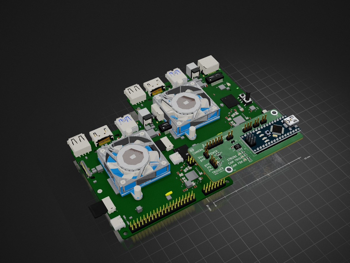
Camera controller is an open-source printed circuit board by ExcessiveOverkill, from the ExcessiveOverkill/strobe-camera repository on GitHub. It is a 2-layer board of 82 × 35 mm with 28 parts on 42 nets, routed with 136 tracks and 79 vias.
It is built around the THVD1420D and D1213A-04S-7-ES. Its parts include 8 resistors, 5 diodes, 5 connectors, 2 ICs and 2 switches. It belongs with the AVR (ATmega, ATtiny) boards of this library.
This repository contains the KiCad files for a high-power pulsed LED strobe board used for very short, very bright flashes during camera exposure.
Project video:
Video script and notes:
strobe camera.mdMain project folder:
KiCad/strobe-light/Manufacturing outputs:
KiCad/strobe-light/manufacturing outputs/Included fabrication files:
*-F_Cu.gbr, *-B_Cu.gbr, mask, paste, silkscreen, edge cuts)*-PTH.drl, *-NPTH.drl)*.gbrjob)KiCad/strobe-light/strobe-light.kicad_pro/strobe-light.kicad_pro.csvNotes:
KiCad/strobe-light/manufacturing outputs/.The camera controller board in KiCad/camera-controller/ is included for reference, but it currently needs fixes before it should be considered production-ready.
Don't stare at the light.
| Qty | Value | Footprint | References |
|---|---|---|---|
| 6 | 1k | Resistor_SMD:R_0603_1608Metric | R1, R2, R3, R4, R7, R10 |
| 4 | LED | LED_SMD:LED_0603_1608Metric | D1, D2, D4, D5 |
| 2 | 0 | Resistor_SMD:R_0603_1608Metric | R5, R6 |
| 2 | MountingHole_Pad | MountingHole:MountingHole_3.2mm_M3_DIN965_Pad_TopBottom | H1, H2 |
| 2 | SW_Push | Connector_PinHeader_2.54mm:PinHeader_1x02_P2.54mm_Vertical | SW1, SW2 |
| 1 | 24v | Connector_PinHeader_2.54mm:PinHeader_1x02_P2.54mm_Vertical | J2 |
| 1 | Arduino_Nano_v3.x | Module:Arduino_Nano | A1 |
| 1 | C | Capacitor_SMD:C_0603_1608Metric | C1 |
| 1 | D1213A-04S-7 | footprints:SOT-363_DIO | U1 |
| 1 | SM712_SOT23 | Package_TO_SOT_SMD:SOT-23 | D3 |
| 1 | THVD1420D | Package_SO:SOIC-8_3.9x4.9mm_P1.27mm | U2 |
| 1 | camera | Connector_PinHeader_2.54mm:PinHeader_1x06_P2.54mm_Vertical | J1 |
| 1 | encoder | Connector_PinHeader_2.54mm:PinHeader_1x03_P2.54mm_Vertical | J5 |
| 1 | strobe | Connector_PinHeader_2.54mm:PinHeader_1x02_P2.54mm_Vertical | J4 |
| 1 | trigger | Connector_PinHeader_2.54mm:PinHeader_1x03_P2.54mm_Vertical | J3 |
The 26 most common of 28 parts.
It measures 82 × 35 mm and has 2 copper layers, 1.6 mm thick.
28 parts, built around the THVD1420D and D1213A-04S-7-ES. The full list of its parts is on this page, with links to each part's symbol and footprint where PCBKit's library has them.
From the ExcessiveOverkill/strobe-camera repository on GitHub, at the commit this page was made from: the board is KiCad/camera-controller/camera-controller.kicad_pcb and its schematic KiCad/camera-controller/camera-controller.kicad_sch. PCBKit opens the board in the browser, with nothing to install.
Its repository states no licence, so its author keeps all rights: ask ExcessiveOverkill before reusing the design.
ExcessiveOverkill/strobe-camera
This repository contains the KiCad files for a high-power pulsed LED strobe board used for very short, very bright flashes during camera exposure.


A-Neal/dmx-led-bar-v1
An FPGA-based 6-channel DMX decoder and LED fixture.

alexanderenrique/smart_tbird
Smart Thunderbird vehicle electronics — ESP32 nodes, alternator delay, display, and tooling.


