2 layers35 × 24 mm
CommonSense
antsouchlos/commonsense-hw
A BLE-based PCB for measuring humidity and temperature
37 partsMIT
 ETH-PBL/WakeMod7
WakeMod: An Open-Source Wake-up Transceiver Module
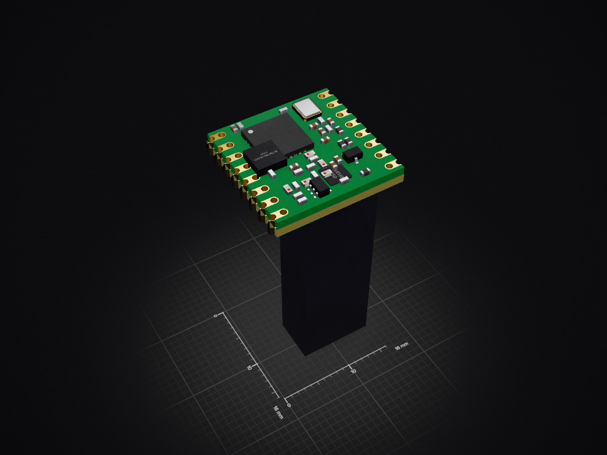
WakeMod is an open-source printed circuit board by ETH-PBL, from the ETH-PBL/WakeMod repository on GitHub. It is a 4-layer board of 16 × 16 mm with 33 parts on 51 nets, routed with 279 tracks and 120 vias.
It is built around the STM32U031K8U6, MAX41462GUB+ and B39871B3744H110, with the LQW03AW11NJ00D, ECS-160-8-36CKM-TR and LQP03HQ22NH02D among its other parts. Its parts include 18 capacitors, 5 ICs, 4 inductors, 2 resistors and 2 connectors. It belongs with the radio and wireless boards and the STM32 boards of this library.


WakeMod is an open-source, ultra-low-power wake-up transceiver module designed for the 868 MHz ISM band, facilitating easy integration of Wake-up Radio (WuR) capabilities into existing and new IoT systems. It aims to significantly reduce idle power consumption while ensuring low-latency event responsiveness, crucial for battery-powered, long-term deployments.
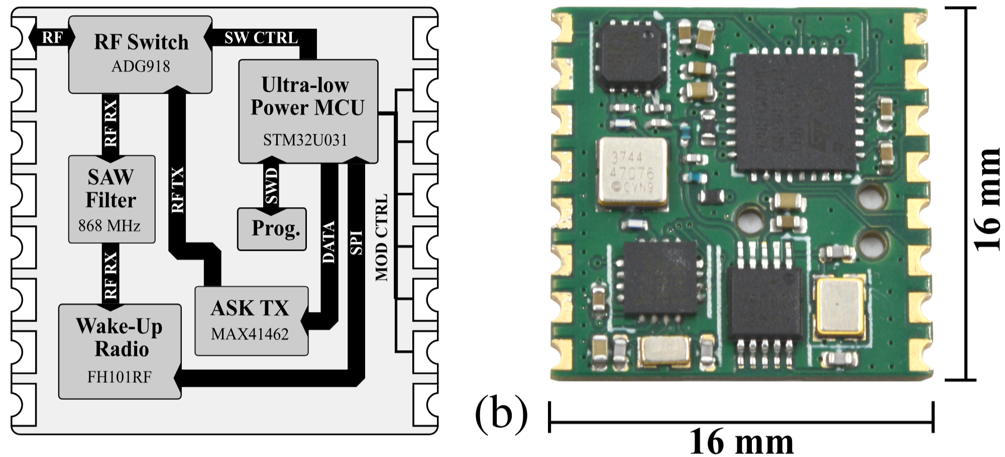
An in-depth analysis of the hardware can be found here: IEEE IWASI / arXiv:2505.21529 (preprint)
Large-scale IoT applications, such as asset tracking and remote sensing, demand multi-year battery lifetimes to minimize maintenance and operational costs. Traditional wireless protocols often employ duty cycling, introducing a tradeoff between latency and idle consumption -- both unsuitable for event-driven and ultra-low power systems. A promising approach to address these issues is the integration of always-on Wake-up Receivers (WuRs). They provide asynchronous, ultra-low power communication to overcome these constraints. This paper presents WakeMod, an open-source wake-up transceiver module for the 868 MHz ISM band. Designed for easy integration and ultra-low power consumption, it leverages the -75 dBm sensitive FH101RF WuR. WakeMod achieves a low idle power consumption of 6.9 µW while maintaining responsiveness with a sensitivity of -72.6 dBm. Reception of a wake-up call is possible from up to 130 m of distance with a -2.1 dBi antenna, consuming 17.7 µJ with a latency below 54.3 ms. WakeMod's capabilities have further been demonstrated in an e-ink price tag application, achieving 7.17 µW idle consumption and enabling an estimated 8-year battery life with daily updates on a standard CR2032 coin cell. WakeMod offers a practical solution for energy-constrained, long-term IoT deployments, requiring low-latency, and on-demand communication.
If you use WakeMod in an academic or industrial context, please cite the following publication:
@inproceedings{schultess25_wakem,
  author         = {Lukas Schulthess and Silvano Cortesi and Michele Magno},
  title          = {Wakemod: a 6.9uw Wake-Up Radio Module With -72.6dbm Sensitivity for On-Demand Iot},
  year           = 2025,
  month          = 7,
  pages          = {1-6},
  booktitle      = {2025 10th International Workshop on Advances in Sensors and Interfaces (IWASI)},
  doi            = {10.1109/iwasi66786.2025.11122000},
  url            = {http://dx.doi.org/10.1109/IWASI66786.2025.11122000},
}SYS_SDN pin.SYS_IRQ) to signal received Wake-up Calls to the host.| Pin Name | Type | Description |
|---|---|---|
VDD | Power | Power Supply Voltage |
GND | Ground | Ground Connection |
SDA | I/O | I2C Data Line |
SCL | Input | I2C Clock Line |
SYS_SDN | Input | System Shutdown / Module Enable. Active Low. High for deep sleep. |
SYS_IRQ | Output | Interrupt Request to Host. Active High. Signals a Wake-up event occurred. |
ANT | RF | Antenna connection |
Note: While the footprint matches RFM69, the interface is I2C, not SPI. All other pins are currently unused.
The firmware architecture of the WakeMod module is optimized for ultra-low power consumption, keeping the STM32U031 MCU in shutdown mode as much as possible. Critical data is retained in backup registers during shutdown.
The MCU wakes up based on three primary sources:
SYS_IRQ pin is then asserted, and the module returns to shutdown.SYS_SDN pin transitions to low, the MCU wakes up and prepares its I2C slave interface to receive commands from the host. When SYS_SDN returns high, the module re-enters shutdown.SYS_SDN is held LOW. The module is operational and ready to accept I2C
commands.SYS_SDN is HIGH. The module enters its lowest power state (STM32U031 in
shutdown, peripherals off). I2C communication is disabled. The FH101RF Wake-up Radio remains functional and
listening. To wake the module for I2C communication, bring SYS_SDN LOW. Allow a short time for the module to initialize before sending I2C commands.SYS_IRQ)SYS_IRQ pin becomes active (HIGH) when the FH101RF detects a valid Wake-up condition (e.g., matching address, pattern received) and the internal STM32U031 has processed this event.IRQ Reason command (0x03) via I2C to determine the cause and retrieve any associated data.IRQ Reason register de-asserts the SYS_IRQ pin. Reading it multiple times will return the same last IRQ reason until a new WuR event occurs.0x2E (7-bit address)SYS_SDN pin is LOW.The WakeMod module supports four main commands initiated by the host MCU:
WhoAmI (0x00): Reads a static device identifier. Used to verify communication.SetupWuR (0x01): Configures the FH101RF Wake-up Radio. This includes setting the 16-bit wake-up address, data rates (low and fast), and IRQ source mask. This command triggers a full calibration of the FH101RF.SendWuC (0x02): Transmits a Wake-up Call (WuC) using the MAX41462 OOK transmitter. This includes the target 16-bit wake-up address, data rates, and an optional 6-byte data payload. The internal STM32U031
uses SPI for accurate timing of the preamble and address/payload transmission to the MAX41462.IRQReason (0x03): Retrieves the reason for the last wake-up event (from the FH101RF) and any received payload data. This data is read from the STM32U031's backup registers.Write Operations (Host to WakeMod):
SetupWuR (0x01) and SendWuC (0x02).0x2E).0x01 for SetupWuR).SendWuC):
START | (0x2E << 1) | W | ACK | <CMD_BYTE (0x02)> | ACK | <Data Byte 0> | ACK | ... | <Data Byte 10> | ACK | STOPRead Operations (Host from WakeMod):
WhoAmI (0x00) and IRQ Reason (0x03).0x2E. Send only 1
byte: the Command Byte (e.g., 0x00 for WhoAmI).0x2E. Read exactly 8
bytes of data from the module (Bytes 0-7 as defined in the table below).WhoAmI):
START | (0x2E << 1) | W | ACK | <CMD_BYTE (0x00)> | ACK | REP_START | (0x2E << 1) | R | ACK | <Read Byte 0> | ACK | ... | <Read Byte 7> | NACK | STOP| Command / Register | Value | Type | Byte 0 | Byte 1 | Byte 2 | Byte 3 | Byte 4 | Byte 5 | Byte 6 | Byte 7 | Byte 8 | Byte 9 | Byte 10 |
|---|---|---|---|---|---|---|---|---|---|---|---|---|---|
| WhoAmI | 0x00 | Read | 0x42 (ID MSB) | 0x42 (ID LSB) | 0x00 (Padding) | 0x00 (Padding) | 0x00 (Padding) | 0x00 (Padding) | 0x00 (Padding) | 0x00 (Padding) | N/A | N/A | N/A |
| SetupWuR | 0x01 | Write | Wake-up Addr [15:8] | Wake-up Addr [7:0] | Low Data Rate (enum) | Fast Data Rate (enum) | IRQ Source Mask | Reserved 0x00 | Reserved 0x00 | Reserved 0x00 | Reserved 0x00 | Reserved 0x00 | Reserved 0x00 |
| SendWuC | 0x02 | Write | Wake-up Addr [15:8] | Wake-up Addr [7:0] | Low Data Rate (enum) | Fast Data Rate (enum) | Send Add. Data Flag (LSb) | Add. Data [0] | Add. Data [1] | Add. Data [2] | Add. Data [3] | Add. Data [4] | Add. Data [5] |
| IRQ Reason | 0x03 | Read | IRQ Source Flags | Recv Add. Data Flag (LSb) | Received Data [0] | Received Data [1] | Received Data [2] | Received Data [3] | Received Data [4] | Received Data [5] | N/A | N/A | N/A |
Table Key:
phy_speed Enum Values table below.SetupWuR (Byte 4) to
enable specific FH101RF interrupt sources, or flags indicating occurred interrupts in IRQ Reason (Byte 0).SendWuC. 1 = Additional Data in Bytes 5-10 (Add. Data [0-5]) is valid and should be sent. 0 = Additional Data is ignored (but bytes 5-10
must still be sent, typically as 0x00).IRQ Reason. 1 = Received Data
in Bytes 2-7 (Received Data [0-5]) is valid. 0 = No valid received data (Bytes 2-7 may be undefined).0x00. They ensure the fixed transaction length.phy_speed Enum Values (as per OLDREADME.md I2C values)These values are used in the SetupWuR and SendWuC commands for the Low/Fast Data Rate bytes.
| Value (for I2C) | Speed (bps) |
|---|---|
| 0x02 | 1024 |
| 0x03 | 2048 |
| 0x04 | 4096 |
| 0x05 | 8192 |
| 0x06 | 16384 |
| 0x07 | 32768 |
Note: For OOK transmission via MAX41462, data rates below 1024 bps (e.g., 256, 512 bps) do not work due to the MAX41462's auto-shutdown functionality. The FH101RF itself supports these lower rates for reception.
SetupWuR / Byte 0 in IRQ Reason)This byte indicates the cause of the interrupt (IRQ Reason) or configures which FH101RF events can cause an interrupt (SetupWuR). Multiple bits can be set. These bits correspond to the FH101RF's interrupt
sources.
| Bit | Description | Notes (Primarily for FH101RF internal events) |
|---|---|---|
| 7 | Cyclic Timer Alarm | Cyclic timer target reached. |
| 6 | RTC Timer Alarm | One of the 4 RTC timers reached its target. |
| 5 | ID Match & LDR | Valid ID received, followed by transition to LDR mode. |
| 4 | ID Match & FIFO Filled | Valid ID received, followed by FIFO being filled. |
| 3 | Correlation Pattern Match | OOK data matches selected correlation sequence. |
| 2 | FIFO Buffer Filled | FIFO filled to configured length (e.g. 6 bytes for payload). |
| 1 | FIFO Overflow | More data received than FIFO capacity. |
| 0 | ID Match | Received Fast Data Packet matches configured 16-bit ID. |
VDD and GND are connected. Pull SYS_SDN LOW to enable the module. Wait briefly for startup if it was in deep sleep.WhoAmI (0x00) read sequence. Check for 0x4242 in
the first two bytes.SetupWuR (0x01) write sequence with:
Wake-up Address.Low Data Rate and Fast Data Rate (see phy_speed enum).IRQ Source Mask to enable interrupts for relevant events (e.g., bit 0 for ID Match, bit 4
for ID Match & FIFO Filled if expecting payload).SYS_IRQ
pin. The WakeMod is now listening. Make sure SYS_SDN is pulled high for WakeMod to enter low-power state.SYS_IRQ goes HIGH:
IRQ Reason (0x03) read sequence (possibly short delay needed before readout).Byte 0 (IRQ Source Flags) to understand why the interrupt occurred.Byte 1 (Recv Add. Data Flag). If its LSB is 1, the 6 bytes of Received Data (Bytes
2-7) are valid. Process this data.IRQ Reason clears the SYS_IRQ pin on the WakeMod.SYS_SDN is LOW.SendWuC (0x02) write sequence with:
Wake-up Address.Low Data Rate and Fast Data Rate.Send Add. Data Flag (set LSB of Byte 4 to 1 if sending payload).Add. Data payload (Bytes 5-10) if applicable.SYS_SDN HIGH to put the WakeMod into its lowest power deep sleep mode. The WuR (FH101RF) remains active.fw/Core/Src: Contains the main source files for the STM32U031 firmware, including main.c, i2c_slave.c (I2C command handling), utils.c (helper functions), and HAL drivers.fw/Core/Inc: Contains the corresponding header files, including main.h, utils.h (definitions, enums).Drivers, Middlewares, etc.) contain STM32CubeMX generated files and libraries.See the LICENSE file of the firmware respective hardware for details.
| Qty | Value | Footprint | References |
|---|---|---|---|
| 6 | 100nF | Capacitor_SMD:C_0402_1005Metric | C2, C8, C11, C15, C16, C17 |
| 4 | 10μF | Capacitor_SMD:C_0402_1005Metric | C3, C7, C12, C18 |
| 4 | 16pF | Capacitor_SMD:C_0402_1005Metric | C9, C10, C13, C14 |
| 1 | 0Ohm | Resistor_SMD:R_0201_0603Metric | R1 |
| 1 | 100pF | Capacitor_SMD:C_0201_0603Metric | C4 |
| 1 | 11nH | Inductor_SMD:L_0201_0603Metric | L3 |
| 1 | 16MHz | Oscillator:Oscillator_SMD_SeikoEpson_SG210-4Pin_2.5x2.0mm | Y2 |
| 1 | 2.2kOhm | Resistor_SMD:R_0402_1005Metric | R2 |
| 1 | 22nH | Inductor_SMD:L_0201_0603Metric | L1 |
| 1 | 2pF | Capacitor_SMD:C_0201_0603Metric | C1 |
| 1 | 3.3pF | Capacitor_SMD:C_0201_0603Metric | C6 |
| 1 | 30nH | Inductor_SMD:L_0201_0603Metric | L2 |
| 1 | 32.768kHz | sc-crystal:ECS_ECX-12R | Y1 |
| 1 | 4.7pF | Capacitor_SMD:C_0201_0603Metric | C5 |
| 1 | 5.6nH | Inductor_SMD:L_0201_0603Metric | L4 |
| 1 | ADG918BCPZ | Package_CSP:LFCSP-8-1EP_3x3mm_P0.5mm_EP1.45x1.74mm | U1 |
| 1 | B39871B3744H110 | sc-ic:QUALCOMM_B3744 | U2 |
| 1 | FH101RF | sc-ic:RFICIENT_QFN-16 | U3 |
| 1 | MAX41462 | sc-ic:MAXIM_MINI-SO-10 | U4 |
| 1 | RFM22_MODULE | sc-connector:RFM22_MODULE | J2 |
| 1 | STM32U031K8U6 | Package_DFN_QFN:QFN-32-1EP_5x5mm_P0.5mm_EP3.45x3.45mm | U5 |
| 1 | SWD | sc-connector:TAGCONNECT_TC2030-MCP-NL | J1 |
It measures 16 × 16 mm and has 4 copper layers, 1.06 mm thick.
33 parts, built around the STM32U031K8U6, MAX41462GUB+, B39871B3744H110 and LQW03AW11NJ00D. The full list of its parts is on this page, with links to each part's symbol and footprint where PCBKit's library has them.
From the ETH-PBL/WakeMod repository on GitHub, at the commit this page was made from: the board is hw/wake-mod.kicad_pcb and its schematic hw/connector.kicad_sch. PCBKit opens the board in the browser, with nothing to install.
Its repository states no licence, so its author keeps all rights: ask ETH-PBL before reusing the design.
antsouchlos/commonsense-hw
A BLE-based PCB for measuring humidity and temperature


tactical-snacks/hum_hw
Hour Utilization Monitor using accelerometer and RTC to track run time


a-little-wifi/Tinyriser
Cooler/cuter riser for Lenovo 8th/9th gen Tiny5 PCs

Cimos/kicad-druid
KiCad custom design rules (.kicad_dru) matching JLCPCB and PCBWay manufacturing capabilities

