2 layers100 × 100 mm

 ep2k/epFC3
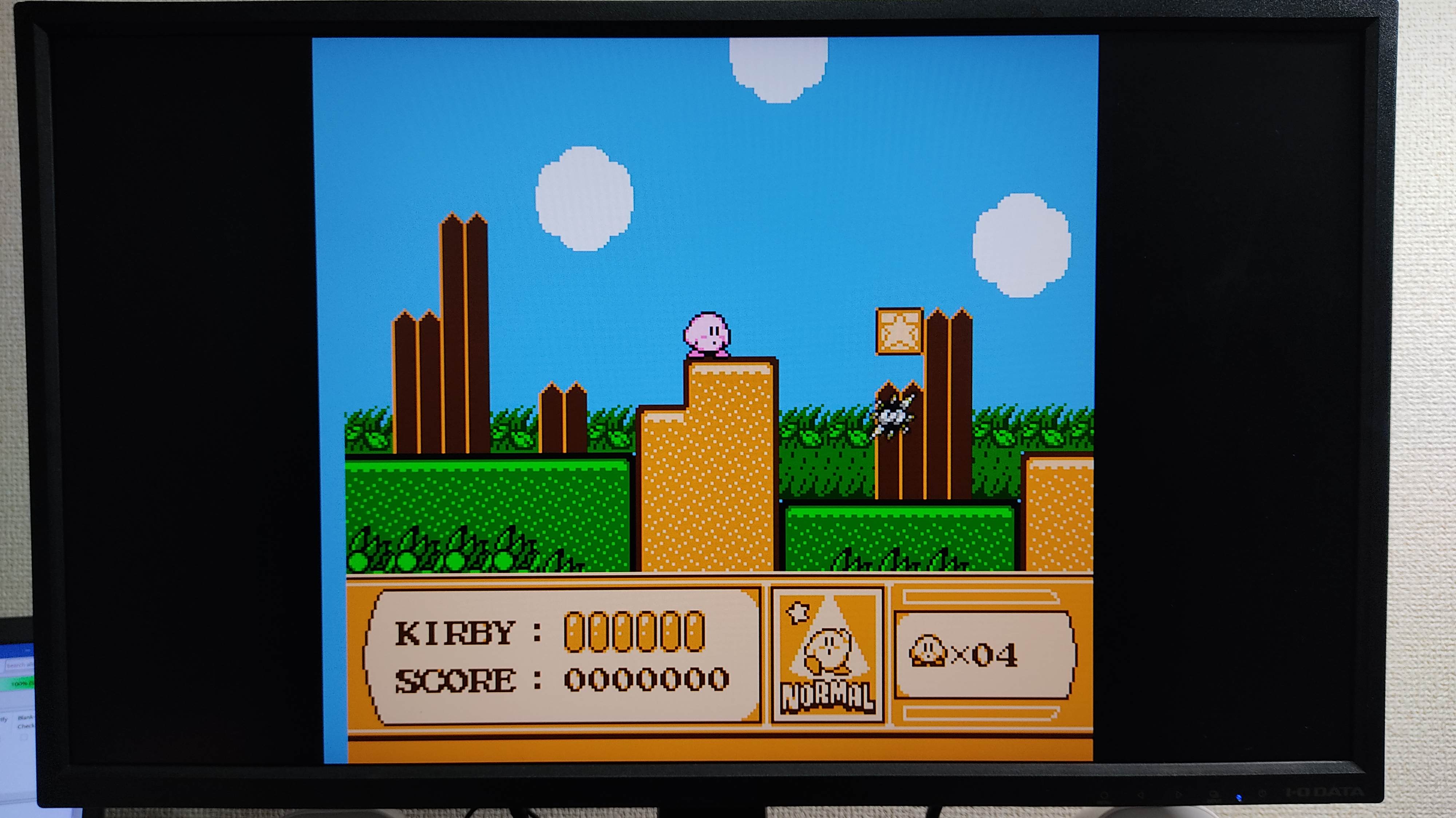
Family Computer emulator running on an FPGA
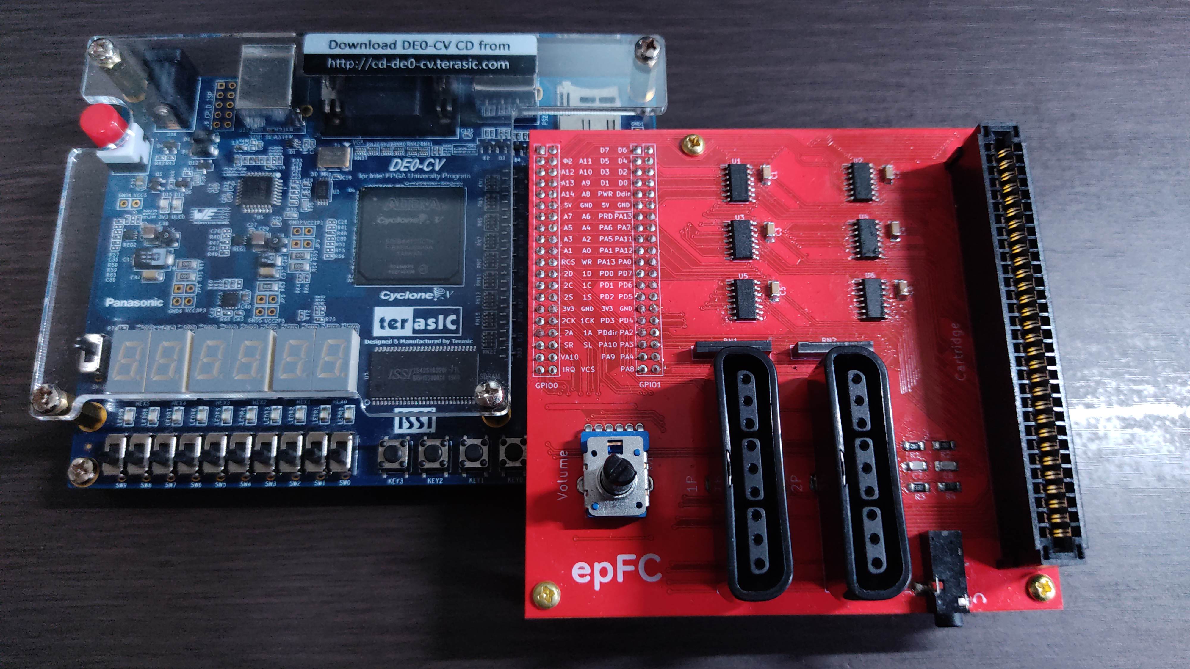
EpFC de0cv is an open-source printed circuit board by ep2k, from the ep2k/epFC repository on GitHub, published under the GPL-3.0 licence. It is a 2-layer board of 100 × 100 mm with 47 parts on 139 nets, routed with 1,332 tracks and 304 vias.
It is built around the 74HCT04D and SJ-3523-SMT-TR. Its parts include 15 capacitors, 9 resistors, 8 ICs and 4 connectors. It belongs with the fPGA and programmable logic boards of this library.


epFC is an implementation of Nintendo's Family Computer (Nintendo Entertainment System) written in SystemVerilog. It works on an FPGA board with a board for connection to Famicom cartridges.
It has no built-in mappers except for NROM, and can basically only operate in real-time communication with cartridges.
The operation has been confirmed with Terasic DE0-CV Board.
| Qty | Value | Footprint | References |
|---|---|---|---|
| 10 | 0.1u | Capacitor_SMD:C_1206_3216Metric_Pad1.33x1.80mm_HandSolder | C1, C2, C3, C4, C5, C6, C9, C10, C11, C12 |
| 6 | 74HCT04 | Package_SO:SOIC-14_3.9x8.7mm_P1.27mm | U1, U2, U3, U4, U5, U6 |
| 3 | 3.3k | Resistor_SMD:R_1206_3216Metric_Pad1.30x1.75mm_HandSolder | R3, R4, R7 |
| 3 | 30p | Capacitor_SMD:C_1206_3216Metric_Pad1.33x1.80mm_HandSolder | C7, C8, C13 |
| 2 | 100p | Capacitor_SMD:C_1206_3216Metric_Pad1.33x1.80mm_HandSolder | C14, C15 |
| 2 | 22k | Resistor_SMD:R_1206_3216Metric_Pad1.30x1.75mm_HandSolder | R8, R9 |
| 2 | 2k | Resistor_SMD:R_1206_3216Metric_Pad1.30x1.75mm_HandSolder | R1, R2 |
| 2 | 420 | Resistor_THT:R_Array_SIP6 | RN1, RN2 |
| 2 | 74LVCC3245 | Package_SO:SO-24_5.3x15mm_P1.27mm | U7, U8 |
| 2 | DE0-CV_GPIO | _epFC_de0cv:PinSocket_2x20_P2.54mm_Vertical_Back | GPIO0, GPIO1 |
| 2 | DUALSHOCK_Port | _epFC_de0cv:DUALSHOCK_Port | J1, J2 |
| 1 | 1.5k | Resistor_SMD:R_1206_3216Metric_Pad1.30x1.75mm_HandSolder | R6 |
| 1 | 10k | _epFC_de0cv:Potentiometer_Bourns_PTV112 | RV1 |
| 1 | 1k | Resistor_SMD:R_1206_3216Metric_Pad1.30x1.75mm_HandSolder | R5 |
| 1 | Famicom_Card_Edge_Connector | _epFC_de0cv:Famicom_Card_Edge_Connector | J4 |
| 1 | LOGO | _epFC_de0cv:epFC | G*** |
| 1 | LOGO | _epFC_de0cv:headphone | G*** |
| 1 | SJ-3523-SMT-TR | SJ-3523-SMT-TR:CUI_SJ-3523-SMT-TR | J3 |
The 43 most common of 47 parts.
It measures 100 × 100 mm and has 2 copper layers, 1.6 mm thick.
47 parts, built around the 74HCT04D and SJ-3523-SMT-TR. The full list of its parts is on this page, with links to each part's symbol and footprint where PCBKit's library has them.
From the ep2k/epFC repository on GitHub, at the commit this page was made from: the board is KiCad/epFC_de0cv/epFC_de0cv.kicad_pcb and its schematic KiCad/epFC_de0cv/epFC_de0cv.kicad_sch. PCBKit opens the board in the browser, with nothing to install.
Its repository publishes it under the GPL-3.0 licence: you may reuse it on that licence's terms (keep the author's notice, and for a copyleft licence share your changes alike).


zueblin/Polaron
A DIY drum machine for the teensy microcontroller (hardware / software)


pa3gsb/Radioberry-2.x-extensions
Hardware extensions to the Radioberry Ham Radio

wiretap-retro/Gameboy-DMG-Headphone-Jack-PCB
A replacement Gameboy DMG headphone jack PCB utilizing all newly manufactured parts -- yes, even the jack.
