Skip to the content
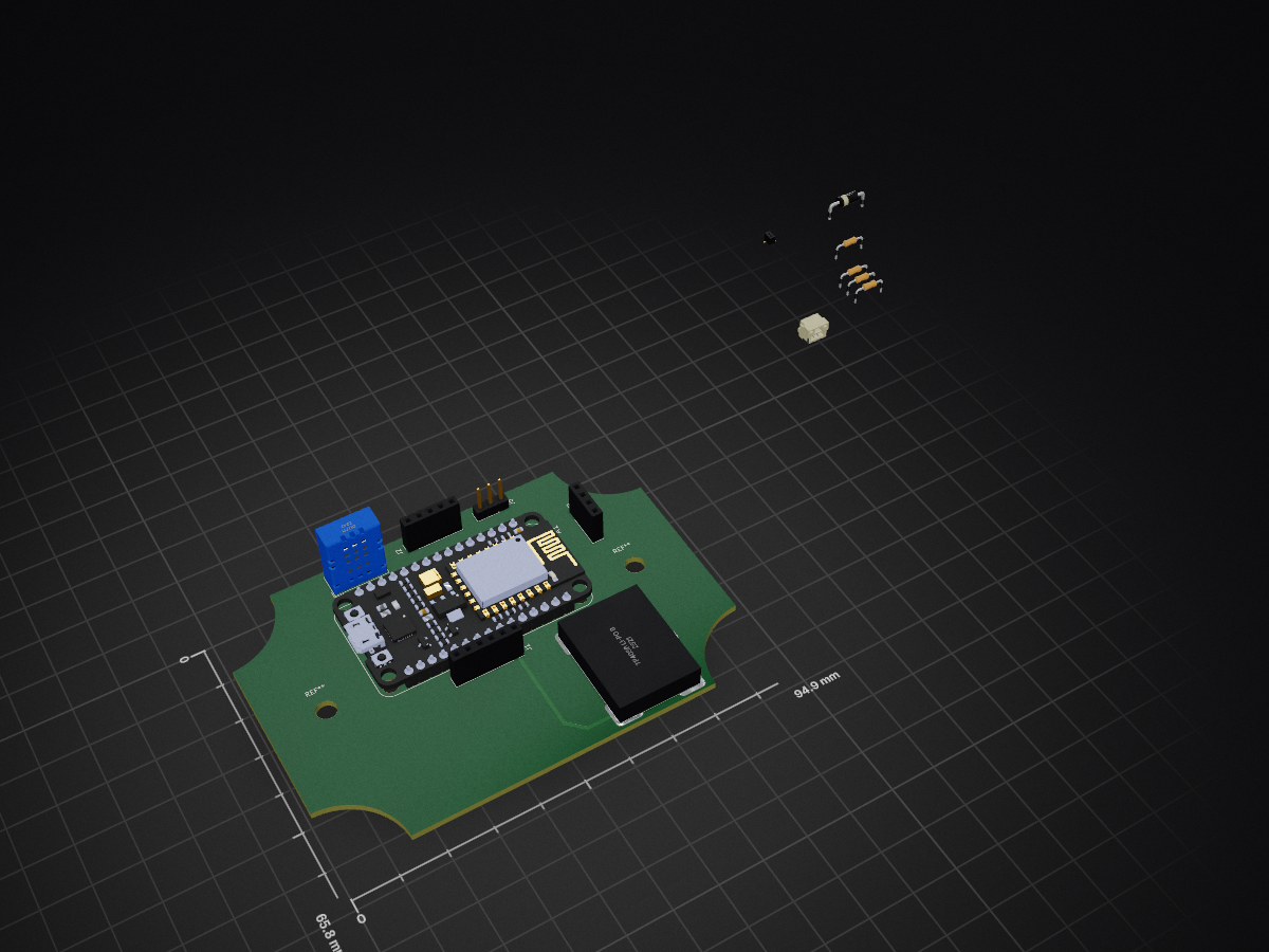
2 layers94.9 × 65.8 mmAutomatic Watering System, the printed circuit board in 3D

The Automatic Watering System is a smart IoT solution for plant care, built using ESP8266 microcontrollers. The system provides automated plant monitoring and watering capabilities with a web-based interface for…

Size
94.9 × 65.8 mm
Copper layers
2
Thickness
1.6 mm
Parts
16
Nets
37
Pads
78
Tracks, vias
10, 0
Routed
Yes
KiCad
KiCad 8.0 (file 20240108)
Created
22 Sep 2024
Updated
15 Feb 2026

Overview

Automatic Watering System is an open-source printed circuit board by EmmanuelAhonle1, from the EmmanuelAhonle1/Automatic-Watering-System repository on GitHub. It is a 2-layer board of 94.9 × 65.8 mm with 16 parts on 37 nets, routed with 10 tracks and 0 vias.

It is built around the DHT11. Its parts include 4 resistors, 3 connectors, 2 ICs and 2 diodes.

Main components

1

README

README.md

Automatic Watering System

Overview

The Automatic Watering System is a smart IoT solution for plant care, built using ESP8266 microcontrollers. The system provides automated plant monitoring and watering capabilities with a web-based interface for configuration and monitoring.

Hardware Components

  • ESP8266 Microcontroller
  • DHT11 Temperature and Humidity Sensor (Pin D5)
  • Capacitive Soil Moisture Sensor (Pin D3)
  • VEML7700 Ambient Light Sensor (Pins D4(SCL), D9(SDA))
  • LC709203F Battery Level Sensor (Pins D6(SCL), D7(SDA))
  • RGB Status LED (Pins D0(R), D1(G), D2(B))
  • All components are defined in Pinouts.hpp

Setup (IMPORTANT!!!)

For detailed setup instructions, check out the setup guide.

Features

1. WiFi Configuration and Management

  • Captive portal for initial WiFi setup
  • Automatic reconnection handling
  • OTA (Over-the-Air) update support
  • Access Point mode with DNS server for initial configuration
  • Support for multiple network security types

2. Device Management

  • Unique device naming system
  • Persistent storage of device settings
  • MAC address tracking
  • JSON-based configuration storage

3. Sensor Integration

  • Temperature and humidity monitoring
  • Soil moisture level detection
  • Ambient light measurement
  • Battery level monitoring
  • All sensor readings available through unified interface

4. Status Indication

RGB LED status indicators for:

  • WiFi Connected (Blinking Blue)
  • AP Mode (Solid Red)
  • MySQL Server Connected (Solid Green)
  • Connection Lost (Fast Red Blinking)
  • Reconnecting (Purple Blinking)

5. Web Interface

Three main interfaces:

  1. WiFi Configuration (/wifi_config/)

    • Network scanning
    • Connection management
    • Status display
  2. User Authentication (/intro_login/)

    • User login
    • New user registration
    • Session management
  3. Plant Registration (/plant_registration/)

    • Plant node configuration
    • Species selection
    • Customizable care parameters

Software Architecture

Core Components

  1. WiFi Manager (wifi_manager.hpp, wifi_manager.cpp)

    • Handles all network connectivity
    • Manages access point and station modes
    • Implements captive portal
    • Handles OTA updates
  2. Device Manager (device_manager.hpp, device_manager.cpp)

    • Manages device identification
    • Handles configuration storage
    • Coordinates settings updates
  3. Data Acquisition (dataAcquisition.hpp, dataAcquisition.cpp)

    • Interfaces with all sensors
    • Provides unified data reading interface
    • Handles sensor calibration and thresholds
  4. Database Communication (DatabaseCommands.hpp, DatabaseCommands.cpp)

    • Manages API interactions
    • Handles data synchronization
    • Implements connection monitoring
  5. RGB Status Handler (rgb_status.hpp, rgb_status.cpp)

    • Manages visual feedback
    • Implements state machine for status indication
    • Handles LED control

Web Interface

The system provides three main web interfaces:

  1. WiFi Configuration

    • Network scanning and selection
    • Password input
    • Connection status display
  2. User Authentication

    • Login interface
    • Registration form
    • Session management
  3. Plant Registration

    • Plant species selection
    • Watering frequency configuration
    • Environmental threshold settings

Setup and Configuration

Initial Setup

  1. Flash the ESP8266 with the firmware
  2. Power on the device
  3. Connect to the device's AP (Format: "PlantNode-XXXX")
  4. Navigate to the captive portal
  5. Configure WiFi settings

Plant Registration

  1. Login or create an account
  2. Configure plant parameters:
    • Node name
    • Plant species
    • Watering frequency
    • Environmental thresholds
  3. Save configuration

API Integration

The system integrates with a REST API for:

  • User authentication
  • Plant node registration
  • Settings synchronization
  • Data logging

API endpoints are defined in dbQueryCreator.hpp and configured via config.h

Development

Requirements

  • Arduino IDE or PlatformIO
  • ESP8266 board support
  • Required Libraries:
    • ESP8266WiFi
    • ESP8266WebServer
    • ArduinoJson
    • DHT sensor library
    • VEML7700 library
    • LC709203F library
    • RGBLed library

Building

  1. Clone the repository
  2. Install required libraries
  3. Configure config.h with API credentials (Refer to the setup guide)
  4. Build and flash to ESP8266

Security Features

  • Secure WiFi configuration
  • Password protection
  • Session management
  • API authentication
  • OTA update support

Troubleshooting

LED Status Indicators

  • Solid Red: AP Mode (Initial setup required)
  • Blinking Blue: Connected to WiFi
  • Solid Green: Fully connected (WiFi + Database)
  • Fast Red Blinking: Connection lost
  • Purple Blinking: Attempting to reconnect

Common Issues

  1. Connection Failures

    • Check WiFi credentials
    • Verify API availability
    • Monitor LED status
  2. Sensor Readings

    • Verify sensor connections
    • Check pin configurations
    • Validate sensor thresholds

Contributing

  1. Fork the repository
  2. Create a feature branch
  3. Submit a pull request

License

Authors

Emmanuel Ahonle

Parts

16
QtyValueFootprintReferences
3330Resistor_THT:R_Axial_DIN0204_L3.6mm_D1.6mm_P7.62mm_HorizontalR1, R2, R3
11.2kResistor_THT:R_Axial_DIN0204_L3.6mm_D1.6mm_P7.62mm_HorizontalR4
1113990105NodeMCU_ESP8266:SEEED_113990105A1
11N5817Diode_THT:D_DO-41_SOD81_P10.16mm_HorizontalD2
13.7V 3000mA LiPo BatteryConnector_JST:JST_GH_SM02B-GHS-TB_1x02-1MP_P1.25mm_HorizontalBT1
1Ambient Light SensorConnector_PinSocket_2.54mm:PinSocket_1x05_P2.54mm_VerticalJ2
1DHT11Sensor:Aosong_DHT11_5.5x12.0_P2.54mmU1
1LC709203 BoardConnector_PinSocket_2.54mm:PinSocket_1x06_P2.54mm_VerticalJ1
1STATUS_LEDConnector_PinSocket_2.54mm:PinSocket_1x04_P2.54mm_VerticalD1
1Soil Moisture SensorConnector_PinHeader_2.54mm:PinHeader_1x03_P2.54mm_VerticalJ5
1Solar_CellsConnector_PinSocket_1.00mm:PinSocket_1x02_P1.00mm_Vertical_SMD_Pin1LeftSC1
1TP4056 Li-Po Battery Charger ModulePower Management:TP4056 1A Li-ion Battery Charging ModuleU3

The 14 most common of 16 parts.

Similar boards

  • 2 layers96.6 × 82.8 mmStarbie, the printed circuit board in 3D

    Starbie

    SharKingStudios/Starbie

    Half-Life Week 1 Example Project

    11 parts28MIT
  • 2 layers100 × 50 mmConveyor belt pcb, the printed circuit board in 3D

    Conveyor belt pcb

    lansidev/conveyor-belt

    Miniature 3D printed conveyor belt for simulation and fun working with sensors, all controllable with Raspberry Pi

    22 parts9MIT
  • 2 layers93 × 20 mmWiFi VFD, the printed circuit board in 3D

    WiFi VFD

    ciisaichan/WiFi-VFD

    开源的ESP8266驱动VFD屏电路,支持BiliBili粉丝数、时间、温度、湿度

    23 parts8MIT
  • 2 layersOpenMQTTGatewayPCB, the printed circuit board in 3D

    OpenMQTTGatewayPCB

    ebrithiljonas/OMG_PCB

    All in One PCB for the OpenMQTTGateway Project

    36 parts7GPL-3.0
  • 2 layers62 × 19.3 mmSniffingTrinket, the printed circuit board in 3D

    SniffingTrinket

    GeorgK/SniffingTrinket

    A room climate monitor using the Adafruit Trinket Pro

    23 parts6GPL-3.0
  • 2 layersArduino relay, the printed circuit board in 3D

    Arduino relay

    bhaskar9980/Guardian

    Guardian is an advanced, fully automated hydroponics system designed to optimize plant growth and maximize yield.

    58 parts5MIT
  • 2 layers100 × 43.5 mmFirefly, the printed circuit board in 3D

    Firefly

    Twistx77/Firefly

    Open WIFI-enabled RGB lamp with temperature, humidity, suspended air particles and eCO2 sensors.

    33 parts5GPL-3.0
  • 2 layers30.5 × 77.5 mmProyecto sensor temperatura, the printed circuit board in 3D

    Proyecto sensor temperatura

    unla-investigacion-desarrollo/ecosistema-iot

    Antes de desarrollar el sistema final, realizamos una etapa de exploración donde investigamos y experimentamos con las siguientes tecnologías:

    8 parts5

Questions

How big is the Automatic Watering System PCB?

It measures 94.9 × 65.8 mm and has 2 copper layers, 1.6 mm thick.

What parts does the Automatic Watering System use?

16 parts, built around the DHT11. The full list of its parts is on this page, with links to each part's symbol and footprint where PCBKit's library has them.

Where can I download the Automatic Watering System KiCad files?

From the EmmanuelAhonle1/Automatic-Watering-System repository on GitHub, at the commit this page was made from: the board is hardware/Automatic Watering System/Automatic Watering System.kicad_pcb and its schematic hardware/Automatic Watering System/Automatic Watering System.kicad_sch. PCBKit opens the board in the browser, with nothing to install.

Can I use the Automatic Watering System design in my own project?

Its repository states no licence, so its author keeps all rights: ask EmmanuelAhonle1 before reusing the design.