2 layers35.3 × 17.3 mm
Tiny Solar Supply
futureshocked/KLP4e_Tiny-Solar-Supply
This is the repository for the "Tiny Solar Supply" project.
18 parts3MIT
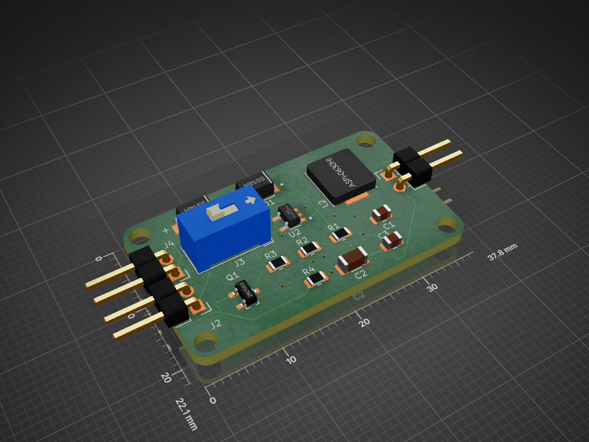
 EmbeddedBytesDev/Tiny-Solar-Power-Supply
A compact solar-powered DC-DC boost converter designed in KiCad 10, based on the Tiny Solar Supply project published by Elektor Magazine.
Tiny Solar Power Supply is an open-source printed circuit board by EmbeddedBytesDev, from the EmbeddedBytesDev/Tiny-Solar-Power-Supply repository on GitHub. It is a 2-layer board of 37.8 × 22.1 mm with 17 parts on 8 nets, routed with 94 tracks and 9 vias.
It is built around the AP3015AKTR-G1, SS14H and ASPI-0630HI-100M-T15. Its parts include 4 resistors, 4 connectors, 3 capacitors, 2 diodes and 1 IC. It belongs with the power boards of this library.


A compact solar-powered DC-DC boost converter designed in KiCad 10, based on the Tiny Solar Supply project published by Elektor Magazine. This project converts the voltage from a single 1.2 V Ni-MH rechargeable battery, charged by a small solar panel, into a regulated 3.3 V DC output suitable for powering low-power embedded systems and IoT devices.
The objective of this project was to gain practical experience in PCB design, schematic capture, component placement, routing, design verification, and version control using Git and GitHub.
The Tiny Solar Supply is built around the AP3015AKTR-G1 micropower boost converter, capable of operating from input voltages as low as 1 V while providing a regulated 3.3 V output. The circuit automatically enables or disables the boost converter depending on the availability of solar power, maximizing battery life and improving energy efficiency.
This implementation includes the complete KiCad project, PCB layout, Gerber files, and project documentation.
| Parameter | Value |
|---|---|
| Solar Input | Small Solar Panel |
| Battery | 1.2 V Ni-MH AA Rechargeable Battery |
| Output Voltage | 3.3 V Regulated |
| Boost Converter | AP3015AKTR-G1 |
| Inductor | 10 µH (ASPI-0630LR-100M-T15) |
| MOSFET | 2N7002 |
| Schottky Diodes | SS14 (x2) |
| PCB Software | KiCad 10 |
The solar panel charges a single-cell Ni-MH battery through an SS14 Schottky diode (D2). While the solar panel is producing power, it pulls the gate of the 2N7002 MOSFET (Q1) high, keeping the AP3015AKTR-G1 boost converter in shutdown mode and preventing unnecessary battery discharge.
When sunlight is no longer available, the solar panel voltage drops, turning the MOSFET off. This pulls the shutdown pin low and enables the boost converter, which steps the battery voltage up to a regulated 3.3 V output for powering external electronics. The output voltage is set by the R1/R2 feedback resistor network:
VOUT = 1.23 × (1 + R1 / R2)| Ref | Part | Footprint |
|---|---|---|
| U1 | AP3015AKTR-G1 | SOT95P280X145-5N |
| Q1 | 2N7002 | SOT-23 |
| D1, D2 | SS14 | D_SMA |
| L2 | ASPI-0630LR-100M-T15 (10 µH) | IND_ASPI-0630LR-100M-T15 |
| R1, R4 | 1 MΩ | R_0805_2012Metric |
| R2 | 604 kΩ, 1% | R_0805_2012Metric |
| R3 | 10 kΩ | R_0805_2012Metric |
| C1 | 4.7 µF, 50 V, X7R | C_0805_2012Metric |
| C2 | 22 µF, 10 V, X7R | C_1206_3216Metric |
| C3 | 10 pF, 50 V, X7R | C_0805_2012Metric |
| J1, J2, J3 | 1x02 pin header, vertical | PinHeader_1x02_P2.54mm_Vertical |
| J4 | 1x02 pin header, horizontal | PinHeader_1x02_P2.54mm_Horizontal |
Both schematic and PCB layout were built and version-controlled stage by stage — full history is in the commit log:
This project provided hands-on experience in:
This project is based on the Tiny Solar Supply design by Clemens Valens, originally published in Elektor Circuit Special 2023. The original article describes a compact solar-powered boost converter using the AP3015/AP3015A DC-DC converter. This repository contains an independent KiCad implementation, PCB layout, project organization, and documentation created for learning and educational purposes.
This repository is shared for educational purposes.
The original circuit design is credited to Elektor Magazine and Clemens Valens. Please refer to the original publication for the source design and associated rights.
| Qty | Value | Footprint | References |
|---|---|---|---|
| 3 | Conn_01x02_Pin | Connector_PinHeader_2.54mm:PinHeader_1x02_P2.54mm_Horizontal | J1, J2, J4 |
| 2 | 1 MOhm | Resistor_SMD:R_0805_2012Metric | R1, R4 |
| 2 | SS14H | SS14H:DIOM4325X250N | D1, D2 |
| 1 | 10 kOhm | Resistor_SMD:R_0805_2012Metric | R3 |
| 1 | 10 pF, 50 V, X7R(0805) | Capacitor_SMD:C_0805_2012Metric | C3 |
| 1 | 22 uF, 10 V, X7R(1206) | Capacitor_SMD:C_1206_3216Metric | C2 |
| 1 | 2N7002 | digikey-footprints:SOT-23-3 | Q1 |
| 1 | 4.7 uF, 50 V, X7R(0805) | Capacitor_SMD:C_0805_2012Metric | C1 |
| 1 | 604 kOhm, 1% | Resistor_SMD:R_0805_2012Metric | R2 |
| 1 | AP3015AKTR-G1 | AP3015AKTR-G1:SOT95P280X145-5N | U2 |
| 1 | ASPI-0630HI-100M-T15 | ASPI-0630HI-100M-T15:IND_ASPI-0630HI-100M-T15 | L2 |
| 1 | Conn_01x02_Pin | Button_Switch_THT:SW_DIP_SPSTx01_Slide_9.78x4.72mm_W7.62mm_P2.54mm | J3 |
The 16 most common of 17 parts.
It measures 37.8 × 22.1 mm and has 2 copper layers, 1.6 mm thick.
17 parts, built around the AP3015AKTR-G1, SS14H and ASPI-0630HI-100M-T15. The full list of its parts is on this page, with links to each part's symbol and footprint where PCBKit's library has them.
From the EmbeddedBytesDev/Tiny-Solar-Power-Supply repository on GitHub, at the commit this page was made from: the board is Tiny Solar Power Supply.kicad_pcb and its schematic Tiny Solar Power Supply.kicad_sch. PCBKit opens the board in the browser, with nothing to install.
Its repository states no licence, so its author keeps all rights: ask EmbeddedBytesDev before reusing the design.
futureshocked/KLP4e_Tiny-Solar-Supply
This is the repository for the "Tiny Solar Supply" project.


akshat-kumar10/solar-supply
The entire circuit and PCB were redesigned from scratch using KiCad EDA, while referring to the original Elektor concept strictly for educational and learning purposes.


chopda15/solar-power-supply
A tiny solar power supply project built with KiCad

dannywarmann/Tiny-Solar-Power-Supply-PCB-Redesign
This project is a learning-focused redesign of Elektor’s Tiny Solar Power Supply

