2 layers116.8 × 30 mm
Type d
google/mozc-devices
Circuit diagrams and firmware source code for Gboard DIY keyboards
14 parts3kApache-2.0

 emard/roomba-wifi9
Roomba to ESP8266 nodemcu adapter PCB
Wifi roomba is an open-source printed circuit board by emard, from the emard/roomba-wifi repository on GitHub. It is a 2-layer board of 73.7 × 50.8 mm with 14 parts on 10 nets, routed with 68 tracks and 0 vias.
Its parts include 3 resistors, 3 diodes, 2 ICs, 1 connector and 1 fuse. It belongs with the radio and wireless and interfaces and adapters boards and the ESP8266 boards of this library.
Wifi remote control interface for the iRobot Roomba vacuum cleaner. Tested on model 880, others 600-900 have similar command set and probably will work too.
telnet to roomba IP while it is charging, it should display something like this:
telnet 192.168.0.2
Trying 192.168.0.2...
Connected to 192.168.0.2.
Escape character is '^]'.
bat:   min 0  sec 10  mV 17061  mA 1016  tenths-deg-C 348  mAH 2696  state 5
bat:   min 0  sec 11  mV 17061  mA 1016  tenths-deg-C 348  mAH 2696  state 5
bat:   min 0  sec 12  mV 17061  mA 1008  tenths-deg-C 348  mAH 2696  state 5
bat:   min 0  sec 13  mV 17061  mA 1023  tenths-deg-C 348  mAH 2696  state 5
To reset roomba to similar state like battery was replaced, type CTRL-G and ENTER. Roomba beeps and prints different messages after reset and again battery charging messages as above.
to exit telnet, type CTRL-] quit ENTER
^]
telnet> quit
python3 script to send "DOCK" command
#!/usr/bin/env python3
import socket
s = socket.socket(socket.AF_INET, socket.SOCK_STREAM)
s.connect(("192.168.0.2",23))
#print(s.recv(256))
#s.send(bytearray([128, 135, 173])) # start, clean, stop
s.send(bytearray([128, 143, 173])) # start, seek dock, stop
s.close()
python3 script to shown 4 chars approximated on 7-segment display:
#!/usr/bin/env python3
import socket, sys, time
disp = sys.argv[1][0:4].encode() # max 4 chars
disp += b" " * (4-len(disp)) # pad length 4 with spaces
s = socket.socket(socket.AF_INET, socket.SOCK_STREAM)
s.connect(("192.168.48.116",23))
s.send(bytearray([128, 131, 174])) # safe mode
time.sleep(0.05)
s.send(bytearray([164])+disp)
s.close()

./roomba.disp.py TEST
Other commands are described in iRobot Roomba 600 Open Interface Spec
Get nodemcu from ebay for $3.5 and flash it with some TCP-serial bridge code.
From Arduino install ESP8266 support from Boards Manager.
set board to "NodeMCU 1.0 (ESP-12E Module)".
open Examples -> ESP8266Wifi -> WifiTelnetToSerial
setup WiFi user and password to connect to local access point and enable "SWAP_PINS" to use hardware serial 115200,8,n,1 connected as RX=gpio13, TX=gpio15 to Roomba:
#define SWAP_PINS 1To compile and write flash, click round blue button with right arrow.
When monitored at USB-serial port, it will print IP address where it connected.
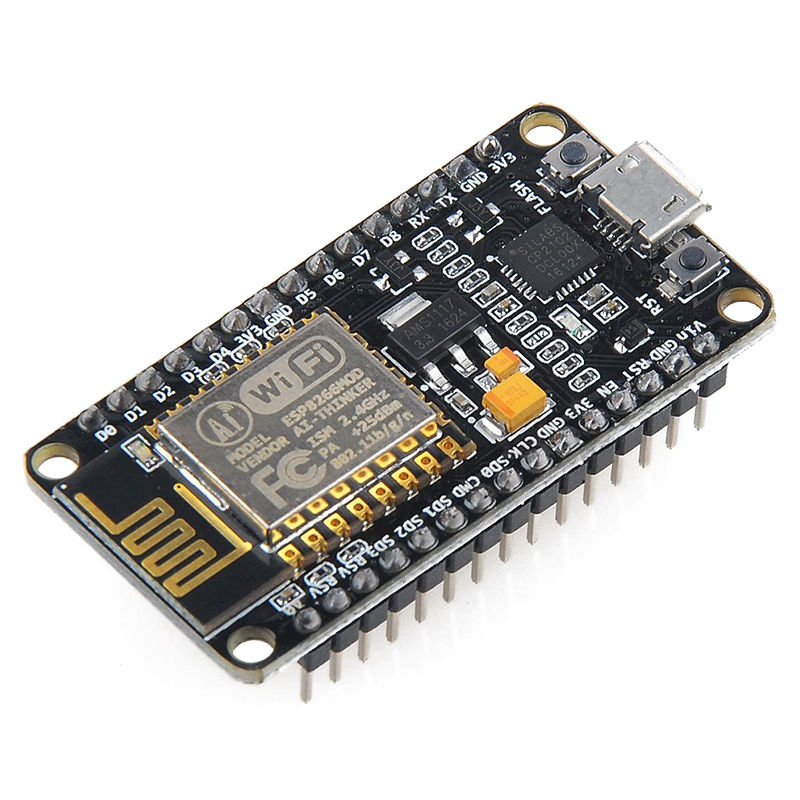
Get 3.3V switching power supply module from ebay for $2:
2A DC 5V-23V to 3.3V DC-DC Step-Down Power Supply Buck Module for esp8266 WiFi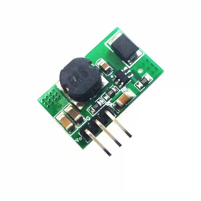
On the back of the module PCB is written:
   Canton-Power
      DC-DC
Step-Down Converter
3.3V[x] 5V[ ] Vi GND VoAdafruit has roomba cable. Also apple or mac 8-pin mini-din cable ordered from ebay will fit to roomba socket (it has extra middle pin which is NC in roomba socket).
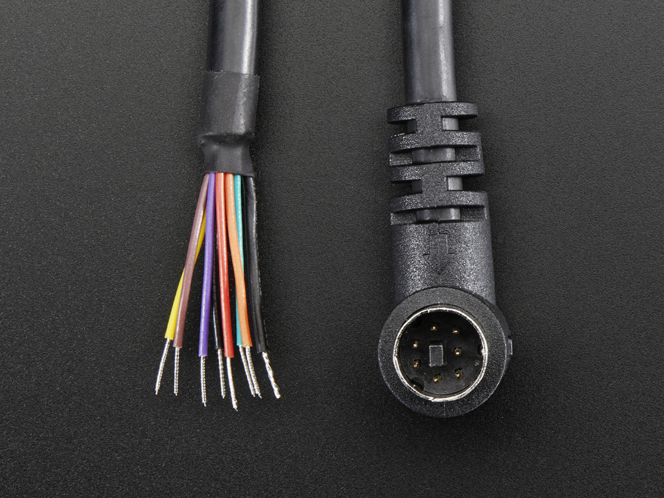
pinout (wire colors inside of apple cable)
1  Vpwr   red    ? no voltage
2  Vpwr   brown  20V
3  RXD    orange input to roomba 5V TTL <- wifi_gpio15
4  TXD    black  output from roomba 5V TTL -> wifi_gpio13
5  DD     yellow wifi_gpio12
6  GND    green
7  GND    blue
8  NC     violet (middle pin)
SHIELD    naked
same pin numbering to DB9 connector
You can order from OSHpark, seeedstudio or similar, email them gerber files and they will send back the PCB:
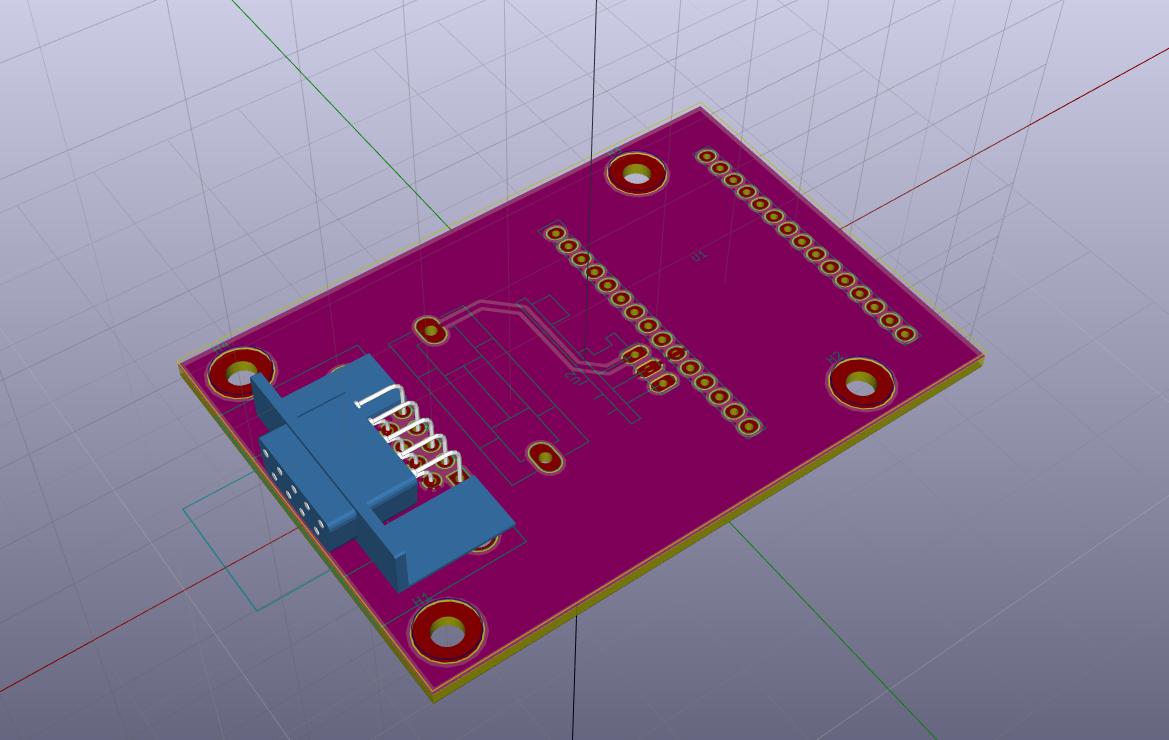
| Qty | Value | Footprint | References |
|---|---|---|---|
| 4 | 3.5mm | Mounting_Holes:MountingHole_3.5mm_Pad | H1, H2, H3, H4 |
| 3 | 220 | Resistors_SMD:R_1206 | R1, R2, R3 |
| 3 | 3V6 | SMD_Packages:SMD-1206_Pol | D1, D2, D3 |
| 1 | DB9 | Connect:DB9FC | J1 |
| 1 | F_Small | Fuse_Holders_and_Fuses:Fuseholder5x20_horiz_SemiClosed_Casing10x25mm | F1 |
| 1 | NodeMCU_1.0 | nodemcu:NodeMCU_1.0 | U1 |
| 1 | SMPS-3V3 | smps-3v3:PINHEAD1-3 | U2 |
google/mozc-devices
Circuit diagrams and firmware source code for Gboard DIY keyboards


hackclub/OnBoard
💡 Join 1,000 teenagers and make your first PCB with a $100 grant!


Twotoz/C5VRX
Ultra-minimal, zero-CPU 5.8 GHz analog FPV video receiver using ESP32-C5 Wi-Fi 6 PHY MODEM_DIAG, BitScrambler WBFM demodulation & resistor DAC CVBS


It measures 73.7 × 50.8 mm and has 2 copper layers, 1.6 mm thick.
14 parts. The full list of its parts is on this page, with links to each part's symbol and footprint where PCBKit's library has them.
From the emard/roomba-wifi repository on GitHub, at the commit this page was made from: the board is wifi-roomba.kicad_pcb. PCBKit opens the board in the browser, with nothing to install.
Its repository states no licence, so its author keeps all rights: ask emard before reusing the design.