


2 layers80 × 56 mm
Gateway
elohimdzangare/Wireless-Sensor-Network
Wireless ESP32 sensor network with deep sleep, ESP-NOW, and live MATLAB visualisation over TCP.
17 parts

Wireless ESP32 sensor network with deep sleep, ESP-NOW, and live MATLAB visualisation over TCP.
Node is an open-source printed circuit board by elohimdzangare, from the elohimdzangare/Wireless-Sensor-Network repository on GitHub. It is a 2-layer board of 52 × 55 mm with 4 parts on 37 nets, routed with 36 tracks and 2 vias.
It is built around the ESP32-DEVKITC-VE and AM2302. Its parts include 3 ICs and 1 connector. It belongs with the sensors and measurement boards and the ESP32 boards of this library.
A wireless environmental monitoring system using battery powered ESP32 sensor nodes that measure temperature, humidity and light across three locations. A central gateway collects everything and sends it to MATLAB for live plotting and logging.

Status: Core system is built and working end to end (nodes to gateway to MATLAB). All three nodes and the gateway have since been redesigned as custom PCBs. Not currently running further test sessions, though one more test run may happen in the future.
Three sensor nodes (Room A, B, C) each have a DHT22 and a BH1750 sensor and run off 4x AA batteries. Each node wakes up from deep sleep, takes a reading, sends it to the gateway over ESP-NOW, tells the gateway how long it's about to sleep for, then powers down again. The gateway stays on all the time, keeps track of all three nodes, manages 8 status LEDs, and forwards everything to MATLAB over TCP so it can be logged and plotted live.
Rooms are just labelled A, B and C for now instead of actual room names, so the sensors can be moved around without having to change any code. A separate note of what each letter actually corresponds to is kept somewhere.
/sensor-network
├── README.md
├── sensor_log.txt
├── /gateway
│   └── gateway_matlab.ino       (final gateway sketch)
├── /node
│   └── sensor_node_final.ino    (final sensor node sketch, used on all 3 nodes)
├── /matlab
│   └── src.m
├── /archive                     (earlier test sketches, kept for reference)
    ├── sensor_test.ino
    ├── sensor_node_test.ino
    ├── gateway_receive_test.ino
    ├── gateway_receive_final.ino
    └── hotspot_connection_test.ino
├── /images                     (images of the network)
    ├── Full Network.jpg
    ├── Gateway 3D Render.png
    ├── Gateway PCB Layout.png
    ├── Gateway.jpg
    ├── Node 3D Render.png
    ├── Node PCB Layout.png
    ├── Sensor Nodes.jpg
├── gateway_schematic.pngThe /archive folder is just earlier versions and one-off test sketches from along the way (testing the sensors before adding ESP-NOW, testing the gateway before connecting it to MATLAB, etc). Not needed to actually run the project, just there to show how it was built up step by step.
| Component | Quantity | Notes |
|---|---|---|
| ESP32 (regular size) | 4 | 3 sensor nodes + 1 gateway |
| DHT22 (AZDelivery) | 3 | Temperature and humidity, one per node |
| BH1750FVI (ARCELI) | 3 | Light level in lux, one per node |
| 4x AA batteries | 3 sets | One set per sensor node, into VIN |
| LEDs | 8 | All status LEDs are on the gateway |
| Resistors | 8 | 470Ω, used for all LEDs regardless of colour |
Sensor power: both sensors on every node need their VCC wired to the ESP32's 3.3V pin, not VIN. VIN is unregulated, so it just passes whatever voltage is feeding it straight through. Wiring a sensor to VIN instead of 3.3V caused issues, more on that in the Debugging section below.
Gateway power: currently running off USB during testing (power bank or laptop). The 5V pin from USB powers the LED circuit. All ESP32 ground pins are tied to a shared ground.
[Node: Room A]  DHT22 + BH1750  ──┐
[Node: Room B]  DHT22 + BH1750  ──┼──(ESP-NOW)──> [Gateway ESP32] ──(TCP, port 8080)──> [MATLAB]
[Node: Room C]  DHT22 + BH1750  ──┘
4x AA, deep sleep connected to WiFi, always onEvery wake cycle goes through setup() from scratch, since deep sleep wipes RAM and there's no way to "resume" where you left off:
MSG_DATA packet and send it to the gateway, including flags for whether each sensor read workedMSG_SLEEP packet saying how long it's about to sleep forEach node currently sleeps for 360 seconds (6 minutes), which works out to 10 readings an hour. Each node tells the gateway its own sleep duration in the sleep message, so if you ever want to change one node's interval you don't need to touch the gateway code at all.
Sensor settling time: right after waking up, the sensors need a moment before their first reading can be trusted, especially the DHT22 which often fails its very first read after power up. The node code adds about a 2 second delay before reading, and retries the DHT22 once if the first attempt comes back invalid.
typedef struct {
  uint8_t  node_id;             // 1 = Room A, 2 = Room B, 3 = Room C
  uint8_t  msg_type;            // 0 = MSG_DATA, 1 = MSG_SLEEP
  float    temperature;         // in °C, -999 if DHT22 failed
  float    humidity;            // in %, -999 if DHT22 failed
  float    lux;                 // -999 if BH1750 failed
  bool     dht_ok;
  bool     bh1750_ok;
  uint32_t sleep_duration_sec;  // only matters when msg_type == MSG_SLEEP
} SensorPacket;
A node always sends a data packet every cycle, even if a sensor failed. The idea is that whether a node can be reached and whether its sensors are actually working should be tracked separately, so a broken sensor doesn't make the whole node look offline. If a reading fails it just gets sent as -999 with the matching _ok flag set to false.
msg_type:
MSG_SLEEP works out when that node should next wake up (current time plus the sleep duration it gave plus a grace window) and turns that node's awake LED offMSG_DATA flashes the RX LED, turns the awake LED back on, updates whether that node has a sensor fault, clears any "unreachable" flag, and forwards the data to MATLABSTATUS:, ERROR: and DATA: messages to Serial and to MATLAB at the same time| LED | Colour | What it does |
|---|---|---|
| Room A RX | Blue | Flashes for 100ms when a packet comes in from Room A |
| Room A Awake/Asleep | White | On while Room A is awake, off once it announces it's sleeping |
| Room B RX | Orange | Flashes for 100ms when a packet comes in from Room B |
| Room B Awake/Asleep | White | On while Room B is awake, off once it announces it's sleeping |
| Room C RX | Yellow | Flashes for 100ms when a packet comes in from Room C |
| Room C Awake/Asleep | White | On while Room C is awake, off once it announces it's sleeping |
| Data Sent (TX to MATLAB) | Green | Flashes for 100ms whenever a message goes out to MATLAB |
| Error | Red | See the error states below |
All the LED flashing is non-blocking. The usual way to blink an LED is digitalWrite(HIGH), then delay(100), then digitalWrite(LOW), but delay() freezes the whole chip for that time, including the part that listens for incoming ESP-NOW packets. So instead, the gateway just remembers what time an LED turned on, and checks on every loop whether 100ms has passed yet to turn it back off. Same blink, but the gateway never actually stops and can't miss a packet while waiting.
| State | Behaviour | What it means |
|---|---|---|
ERROR_NONE | Off | Everything's fine |
ERROR_SENSOR_FAULT | Slow blink, 500ms on/off | A node is still reachable but one of its sensors failed |
ERROR_NODE_UNREACHABLE | Solid on | A node didn't wake up in time, missed its expected window |
If both are happening at once, unreachable wins and the LED goes solid. The reason behind this is that a node going completely silent is worse than one sensor on one node acting up.
| Define | GPIO | LED |
|---|---|---|
A_RX | 27 | Room A Receive |
A_AWAKE | 14 | Room A Awake |
B_RX | 32 | Room B Receive |
B_AWAKE | 33 | Room B Awake |
C_RX | 4 | Room C Receive |
C_AWAKE | 16 | Room C Awake |
HUB_ERROR | 22 | Error |
HUB_RECEIVE | 19 | Data Sent / TX to MATLAB |
| Function | GPIO |
|---|---|
| BH1750 SDA | 26 |
| BH1750 SCL | 27 |
| DHT22 Data | 25 |
When the gateway powers on, it runs through a little self test before doing anything else: every LED pin gets forced LOW first (some GPIO pins can come up HIGH for a moment on boot before any code runs, so this clears that out), then each LED lights up one at a time, then all 8 flash together twice, then everything turns off and normal operation starts.
| Colour | Forward Voltage |
|---|---|
| Red | 2.0-2.2V |
| Blue | 3.0-3.2V |
| White | 3.0-3.2V |
| Yellow | 1.8-2.0V |
| Green | 3.0-3.2V |
| Orange | 1.8-2.0V |
All LEDs are rated for 20mA forward current. A single 470Ω resistor value was used for every LED regardless of colour, just for simplicity. This means they're not all running at the same brightness or current, but it's not really an issue since these are just status indicators and don't need to be especially bright.
All messages are sent line by line from the gateway, to both Serial and to MATLAB over TCP at the same time.
STATUS:GATEWAY_READY
STATUS:ROOMA_SLEEPING:duration=360
STATUS:ROOMA_RECONNECTED
ERROR:ROOMB_TIMEOUT
ERROR:ROOMC_DHT_FAILURE
ERROR:ROOMC_BH1750_FAILURE
DATA:ROOMA:24.50,68.90,73.33DATA:<ROOM>:<temperature>,<humidity>,<lux>, one line per node per readingSTATUS:<ROOM>_SLEEPING:duration=<seconds>, sent right before a node powers downSTATUS:<ROOM>_RECONNECTED, sent if a node that had been flagged unreachable sends data againERROR:<ROOM>_TIMEOUT, a node missed its expected wake up windowERROR:<ROOM>_DHT_FAILURE / ERROR:<ROOM>_BH1750_FAILURE, sent alongside the data line when a sensor on an otherwise working node failsA fixed timeout doesn't really work once nodes are sleeping for minutes at a time, it would keep falsely triggering during completely normal sleep. So instead:
expected_wake_time = millis() + (sleep_duration_sec * 1000) + GRACE_WINDOW_MSERROR:ROOMX_TIMEOUT only fires if that node hasn't sent a data packet by its own expected_wake_timeSTATUS:ROOMX_RECONNECTEDCurrent values:
tcpclient(GATEWAY_IP, 8080)STATUS: gets printed to console with a timestamp and written to the log fileERROR: gets printed to console (in red, via stderr) and written to the log fileDATA: gets parsed into temperature/humidity/lux per room and the live plots get updatedSTATUS/ERROR message into sensor_log.txt, which keeps appending across sessionsThe gateway's IP address can change depending on whatever network it joins, since it's assigned by DHCP. The Serial Monitor must be checked each session and update the IP in the MATLAB script if needed.
A running list of the actual problems hit while building this, since most of them weren't obvious from the code alone.
LED wouldn't light up no matter what Spent ages checking polarity, resistor values, GPIO pin mapping, even swapped pins entirely. Eventually traced it to the breadboard itself. The long breadboard I had purchased had a physical gap splitting the ground rail into two separate halves that aren't actually connected to each other. The ESP32's ground was in one half and the LED circuit's ground was in the other half, so they were never connected despite looking like the same rail. Fixed by bridging both halves with a jumper wire.
BH1750 "device not configured" error, but only sometimes The BH1750 worked fine on a direct 6V supply but kept failing with this error once running off USB. Turned out both sensors had their VCC wired to VIN instead of 3.3V. VIN is unregulated so it just passes through whatever is feeding it, meaning the BH1750 (rated for 2.4 to 3.6V) was actually running at close to 5 or 6V depending on the power source. It happened to behave at 6V but not at 5V from USB, which made it look inconsistent rather than just wrong. Moving both sensors' VCC to the 3.3V pin fixed it completely. This also matters for the battery powered nodes specifically, since a sensor wired to VIN would get less reliable as the battery drains.
GPIO14 turning on by itself before any code ran
Powered on the gateway and noticed one LED was already lit before any sketch had even done anything. Some ESP32 GPIO pins default to a HIGH state for a moment during boot, before setup() runs. Fixed by forcing every LED pin LOW right at the very start of the boot sequence function.
Error LED stuck blinking even while a node was asleep
After adding deep sleep, the gateway kept showing a sensor fault for a node that was just sleeping normally. This was because the gateway didn't yet know how to tell apart a sleep announcement from a regular data packet, so the last reading it saw before the node went quiet (which happened to have a sensor fault from sensors not being settled yet) just stayed stuck. Fixed by adding sensor settling delays on the node side, and by having the gateway properly handle MSG_SLEEP messages separately from MSG_DATA.
sensor_log.txt and reconstruct/replay what happened on any given day, instead of only being able to see things live.Room mapping for this test:
No artificial lighting was used in any room during this test.



No timeouts or sensor faults occurred during this run. Full log available here, room labels here.
The basement (Room B) stayed noticeably more stable in both temperature and humidity than the other two rooms, which makes sense given it's underground and shielded from outdoor temperature swings. The light readings line up well with expected sun position and window placement throughout the afternoon and evening, with the bedroom (Room C) starting brightest from direct sun and dropping off sharply once the sun moved off that window, while the backyard (Room A) decayed more gradually as expected outdoors.
Both the sensor nodes and the gateway have since been redesigned as custom PCBs in KiCad.
Node: Same circuit as the breadboard version (ESP32 DevKitC, DHT22, BH1750), with the addition of a 2-pin battery connector (J1) wired directly to the ESP32's 5V and GND pins, so each node can be powered by a battery through the PCB itself.
Gateway: No schematic changes, only a new PCB layout. The gateway continues to run off the ESP32's USB-C power, same as the breadboard version.
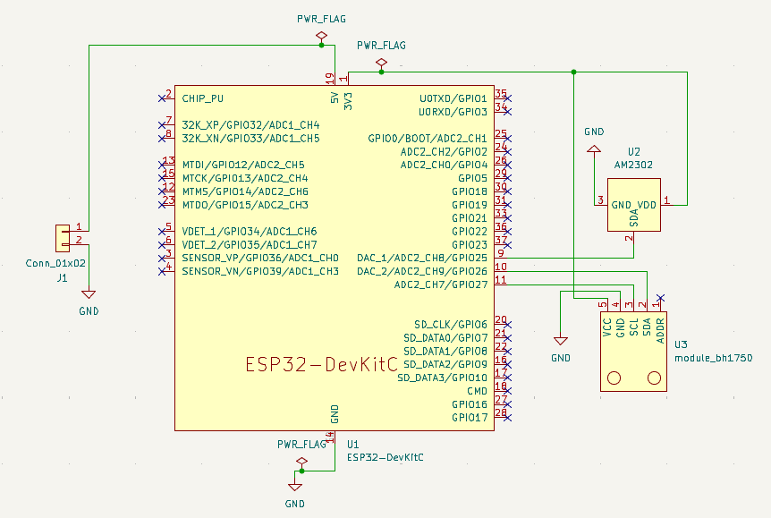
Figure 1: Updated Node Schematic
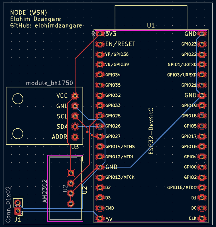
Figure 2: Node PCB Layout
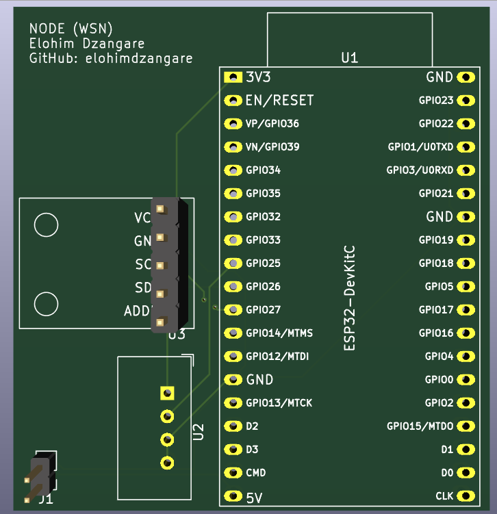
Figure 3: Node PCB 3D Render
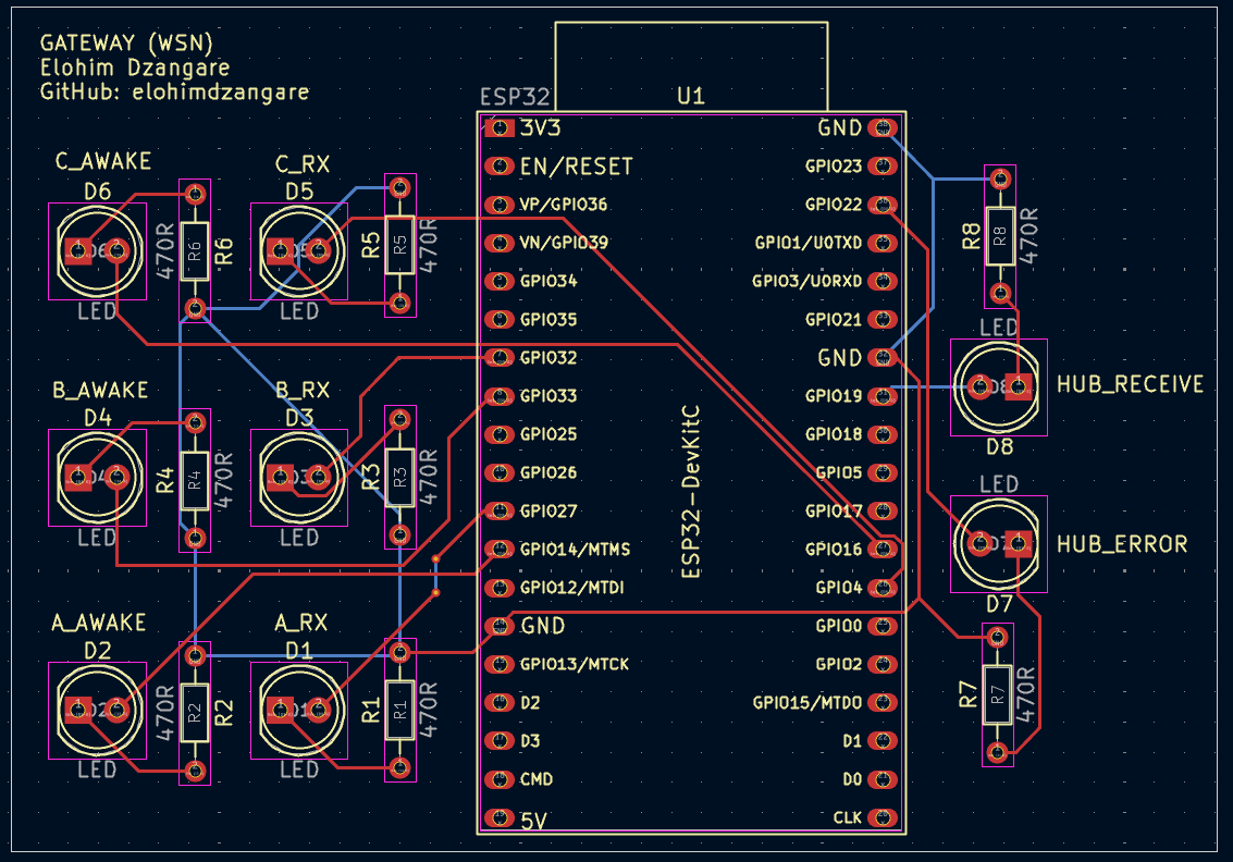
Figure 4: Gateway PCB Layout
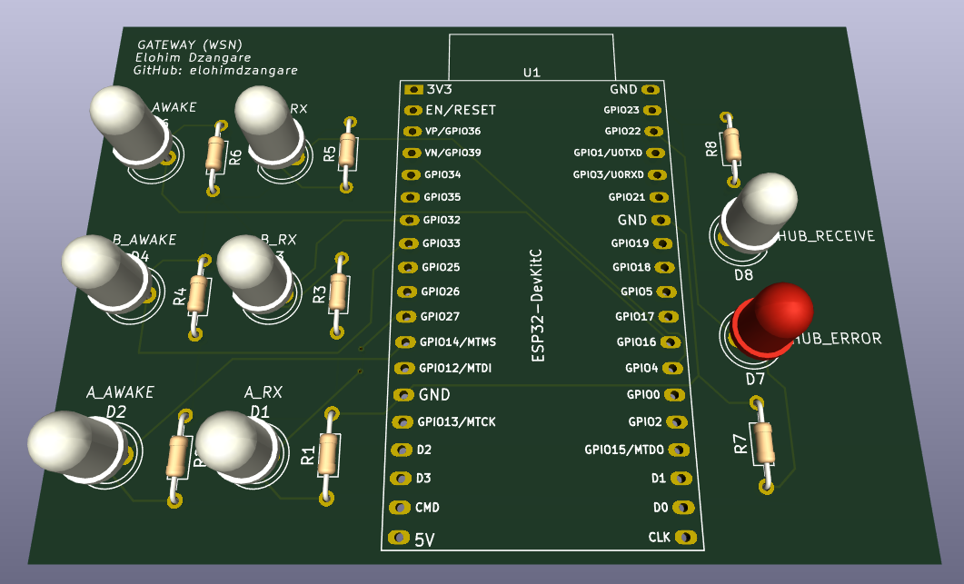
Figure 5: Gateway PCB 3D Render
KiCad project files: WSN KiCad Files
| Qty | Value | Footprint | References |
|---|---|---|---|
| 1 | AM2302 | Sensor:ASAIR_AM2302_P2.54mm_Vertical | U2 |
| 1 | Conn_01x02 | Connector_PinHeader_2.00mm:PinHeader_1x02_P2.00mm_Vertical | J1 |
| 1 | ESP32-DevKitC | PCM_Espressif:ESP32-DevKitC | U1 |
| 1 | module_bh1750 | usini_sensors:module_bh1750 | U3 |
It measures 52 × 55 mm and has 2 copper layers, 1.6 mm thick.
4 parts, built around the ESP32-DEVKITC-VE and AM2302. The full list of its parts is on this page, with links to each part's symbol and footprint where PCBKit's library has them.
From the elohimdzangare/Wireless-Sensor-Network repository on GitHub, at the commit this page was made from: the board is WSN KiCad Files/Node/Node.kicad_pcb and its schematic WSN KiCad Files/Gateway/Gateway.kicad_sch. PCBKit opens the board in the browser, with nothing to install.
Its repository states no licence, so its author keeps all rights: ask elohimdzangare before reusing the design.
elohimdzangare/Wireless-Sensor-Network
Wireless ESP32 sensor network with deep sleep, ESP-NOW, and live MATLAB visualisation over TCP.


OpenHumidistat/hardware
KiCAD design files for PCBs for the OpenHumidistat humidity controller

tjiuce/rover
Rover Navigation Optimization System (R-NOS): An ESP32-powered autonomous robotic prototype designed for real-time environmental monitoring.

Launchpad-Incubator/weather-balloon
The research repository for Launchpad's flat-packed weather balloons.

Aanuoluwap/555blinker
This repository contains electronics design projects created using KiCad.

pasinduh2002/GasGuard
IoT and ML-based LPG monitoring system with ESP32 leak detection, automatic valve shutoff, real-time mobile alerts and refill prediction. Built with React Native, Firebase and Python.

