4 layers47 × 106 mm

 elitetq/hid-controller
Making a custom HID controller PCB for interfacing with operating systems like Windows to play games.
Hid controller pcb is an open-source printed circuit board by elitetq, from the elitetq/hid-controller repository on GitHub. It is a 4-layer board of 129.3 × 113.2 mm with 72 parts on 50 nets, routed with 414 tracks and 173 vias.
It is built around the COM-09032, RT9080-33GJ5 and B3F-1000, with the 10118194-0011LF among its other parts. Its parts include 28 resistors, 16 capacitors, 15 switches, 4 ICs and 4 diodes. It belongs with the STM32 boards of this library.


A custom USB gamepad built on an STM32F103, with a KiCad PCB and STM32 firmware. It has two analog sticks with click switches, a D-pad, face buttons, bumpers, digital triggers and Start/Share buttons.
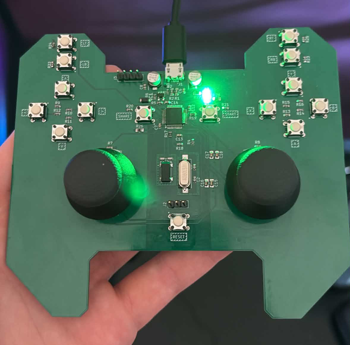
https://github.com/user-attachments/assets/c4e4d3e5-b4be-487b-b6eb-255510382f0a
The device appears as J-Controller, with manufacturer Jonart B and VID:PID 1209:028e. It sends custom HID gamepad reports. The controls follow an Xbox-style layout, but the firmware does not provide native XInput support.
Linux enumerates the controller. Windows only partly enumerates it so far. You can try x360ce for XInput mapping, but Windows needs to detect the controller first. There is no confirmed setup procedure for Windows yet.
| Path | Purpose |
|---|---|
| hid-controller-pcb/ | KiCad schematic, PCB, libraries and BOM |
hid-controller-pcb/production/hid-controller-pcb.zip | Fabrication Gerbers |
hid-controller-code/hid-controller-code/ | Active firmware and Makefile |
Core/Src/main.c inside the firmware folder | ADC sampling, button mapping and report updates |
USB_DEVICE/App/ inside the firmware folder | USB descriptors and HID interface |
usb-backup/ inside the firmware folder | Older firmware copy; not the Makefile's source tree |
assets/ | Photos, PCB layout and video |
Open hid-controller-pcb/hid-controller-pcb.kicad_pro in KiCad. Review the schematic and layout before fabrication. The root board BOM is hid-controller-pcb/BOM.csv; production exports also include production/bom.csv and production/positions.csv. Match the BOM and placement export to the board revision you intend to assemble.
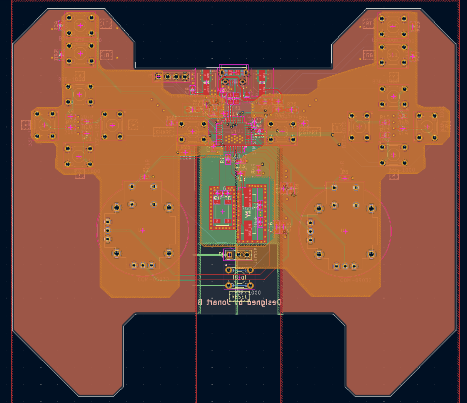
Use the schematic's SWDIO, SWCLK and ground nets for the ST-Link connection, together with target-voltage reference as required by your probe. Check the actual connector orientation against the schematic rather than assuming a standard header pin order.
Requires GNU make, Arm GNU tools (arm-none-eabi-gcc, objcopy and size, including the C library/nano specs), and a POSIX shell for Makefile commands. Flashing requires ST-Link and STM32CubeProgrammer, with STM32_Programmer_CLI on PATH.
NOTE: The firmware folder contains both STM32F103XX_FLASH.ld and STM32F103xx_FLASH.ld. They collide on a normal Windows filesystem. Use a case-sensitive filesystem (for example, a clone inside WSL's Linux filesystem) so both files can be checked out. The Makefile selects STM32F103xx_FLASH.ld.
git clone https://github.com/elitetq/hid-controller.git
cd hid-controller/hid-controller-code/hid-controller-code
make clean
make
The compiler path defaults to /usr/bin/. If your toolchain is elsewhere:
make GCC_PATH=/path/to/arm-toolchain/binOr, if the Arm tools are already on PATH, use make GCC_PATH=. The output is build/hid-controller-code.elf, with .hex and .bin versions alongside it. Clean first so checked-in build artifacts are not reused. There is no specific compiler/programmer version recorded for this build.
Connect ST-Link to the powered target with common ground. From the firmware folder:
STM32_Programmer_CLI -c port=SWD -w build/hid-controller-code.elf -v -rstThis writes the ELF, verifies it and resets the device. The Makefile's make flash target contains a machine-specific Windows programmer path; use the command above or override STMJLINKPATH with your programmer executable. If you build in WSL, make sure the programmer can access ST-Link. You can also copy the ELF to Windows and flash it with STM32CubeProgrammer there.
lsusb -d 1209:028e can check enumeration; then check the inputs separately.If inputs are missing, compare gamepad_update_buttons() and gamepad_update_joysticks() in Core/Src/main.c with the schematic and the report descriptor in USB_DEVICE/App/usbd_custom_hid_if.c. The two stick axes are swapped/inverted in software. Check the inputs on the assembled controller, as enumeration alone does not confirm that the mappings work.
| Qty | Value | Footprint | References |
|---|---|---|---|
| 15 | B3F-1000 | lib:SW_B3F-1000 | S1, S2, S3, S4, S5, S6, S7, S8, S9, S10, S11, S12, S13, S14, S15 |
| 14 | 20kR | Resistor_SMD:R_0603_1608Metric | R9, R10, R11, R12, R13, R14, R15, R16, R20, R21, R22, R23, R24, R25 |
| 5 | 0.1uF | Capacitor_SMD:C_0603_1608Metric | C6, C7, C12, C13, C14 |
| 4 | 0.1uF | Capacitor_SMD:C_0805_2012Metric_Pad1.18x1.45mm_HandSolder | C15, C16, C17, C18 |
| 4 | 1.5kR | Resistor_SMD:R_0603_1608Metric | R3, R4, R7, R8 |
| 2 | 0R | Resistor_SMD:R_0603_1608Metric | R17, R19 |
| 2 | 10uF | lib:CAPAE530X550N | C1, C10 |
| 2 | 22R | Resistor_SMD:R_0805_2012Metric_Pad1.20x1.40mm_HandSolder | R1, R2 |
| 2 | 30pF | Capacitor_SMD:C_0603_1608Metric | C2, C3 |
| 2 | 6pF | Capacitor_SMD:C_0603_1608Metric | C4, C5 |
| 2 | COM-09032 | lib:XDCR_COM-09032 | U3, U4 |
| 2 | LED | LED_SMD:LED_0805_2012Metric | D3, D4 |
| 2 | R_Small | Resistor_SMD:R_0805_2012Metric_Pad1.20x1.40mm_HandSolder | R27, R28 |
| 1 | 10118194-0011LF | lib:10118194-0011LF | J1 |
| 1 | 10kR | Resistor_SMD:R_0805_2012Metric_Pad1.20x1.40mm_HandSolder | R26 |
| 1 | 13kR | Resistor_SMD:R_0603_1608Metric | R6 |
| 1 | 1uF | Capacitor_SMD:C_0603_1608Metric | C8 |
| 1 | 3.4V | lib:SMFA2005CA | D1 |
| 1 | 32.768KHz | lib:XTAL_ABS25-32.768KHZ-6-T | Y2 |
| 1 | 663R | Resistor_SMD:R_0603_1608Metric | R18 |
| 1 | 68kR | Resistor_SMD:R_0603_1608Metric | R5 |
| 1 | 6V | lib:DIODE_VESD05A1B-HD1-GS08_VIS | D2 |
| 1 | 8MHz | lib:ABLS-8.000MHZ-B4-T | Y1 |
| 1 | Jumper | Connector_PinHeader_2.54mm:PinHeader_1x03_P2.54mm_Vertical | J2 |
| 1 | RT9080-33GJ5 | lib:RT9080-33GJ5 | IC1 |
| 1 | STLink | Connector_PinHeader_2.54mm:PinHeader_1x04_P2.54mm_Vertical | J3 |
| 1 | STM32F103C8Tx | Package_QFP:LQFP-48_7x7mm_P0.5mm | U1 |
It measures 129.3 × 113.2 mm and has 4 copper layers, 1.6 mm thick.
72 parts, built around the COM-09032, RT9080-33GJ5, B3F-1000 and 10118194-0011LF. The full list of its parts is on this page, with links to each part's symbol and footprint where PCBKit's library has them.
From the elitetq/hid-controller repository on GitHub, at the commit this page was made from: the board is hid-controller-pcb/hid-controller-pcb.kicad_pcb and its schematic hid-controller-pcb/hid-controller-pcb.kicad_sch. PCBKit opens the board in the browser, with nothing to install.
Its repository states no licence, so its author keeps all rights: ask elitetq before reusing the design.


hackclub/OnBoard
💡 Join 1,000 teenagers and make your first PCB with a $100 grant!


merlindorin/esp32-fan-controller
A small KiCad board to keep my home server cabinet cool. 4 PWM fans, 4 temperature probes, one ESP32.

oresat/oresat-kicad
All things KiCAD for OreSat; libraries, tools, settings, etc.