Dotglow v1 is an open-source printed circuit board by ElectroIoT, from the ElectroIoT/DotGlow-ESP32 repository on GitHub, published under the MIT licence. It is a 2-layer board of 128 × 33 mm with 41 parts on 57 nets, routed with 270 tracks and 195 vias.
It is built around the 74AHCT125D, ESP32-S3-WROOM-1-N16R8 and DHT22, with the USBLC6-2SC6 and XC6220B331MR-G among its other parts. Its parts include 10 resistors, 8 capacitors, 7 connectors, 5 ICs and 3 switches. It belongs with the radio and wireless and lEDs and displays boards and the ESP32 boards of this library.
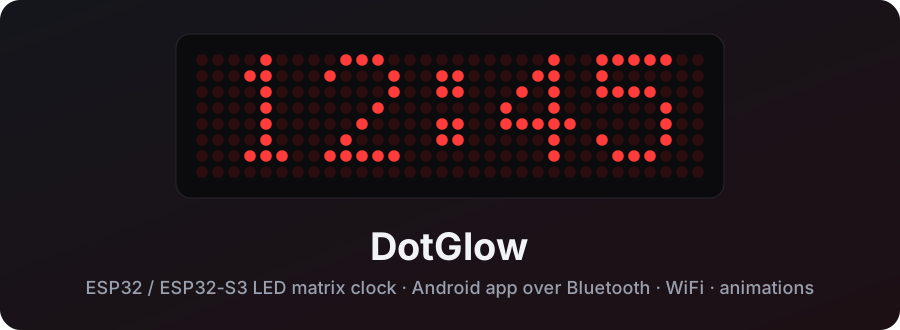
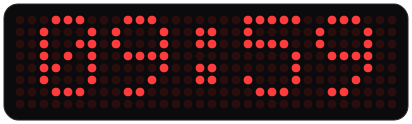
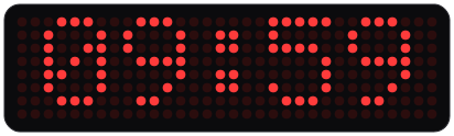
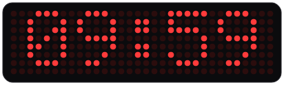
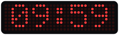
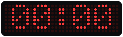
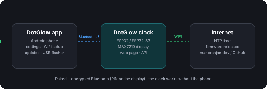
A WiFi + Bluetooth LED matrix clock for ESP32 and ESP32-S3, with its own Android app.
Set it up from your phone in two minutes: no computer, no app accounts, no cloud.
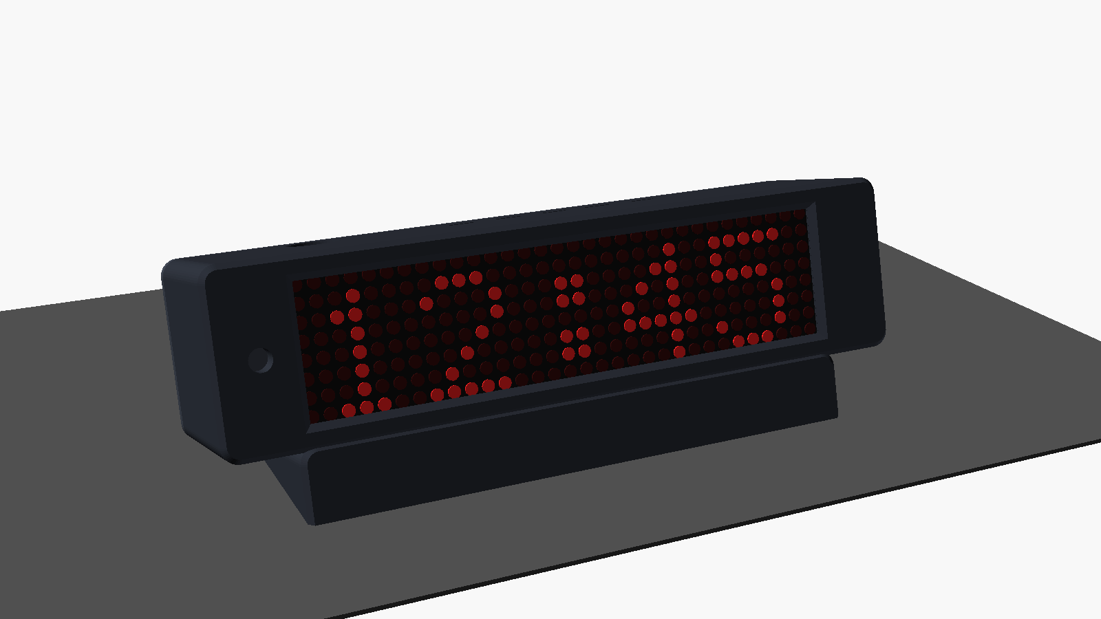
hardware/enclosure: leaning desk case, smoked acrylic front, DC jack; STLs for ESP32-S3, ESP32 DevKit, NodeMCU, D1 mini
Using an ESP8266 / NodeMCU instead? That is the ESP8266 Matrix Clock (WiFi + web page, no Bluetooth). The DotGlow app can install it too.
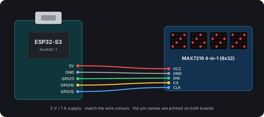
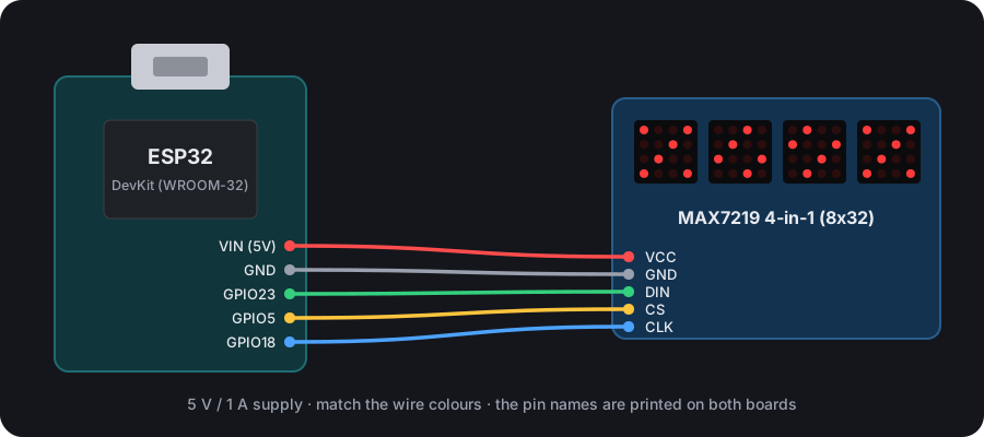
Wiring
ESP32-S3 DevKitC-1
ESP32 DevKit
MAX7219
ESP32-S3
ESP32 DevKit
VCC
5V
VIN (5V)
GND
GND
GND
DIN
GPIO11
GPIO23
CS
GPIO10
GPIO5
CLK
GPIO12
GPIO18
LDR (optional)
GPIO1
GPIO34
Stopwatch button (optional)
GPIO4
GPIO13
Light sensor: LDR from 3V3 to the LDR pin, 10 kΩ from that pin to GND, then turn on Auto brightness.
⚠️ ESP32 DevKit: never use the pins labelled CLK, SD0, SD1, SD2, SD3, CMD. They are the board's flash
memory pins; a wire there stops the board from starting (invalid header: 0xffffffff). The display's CLK goes to
D18, not to the pin called "CLK". Always wire the display's IN end (pins marked DIN), not DOUT.
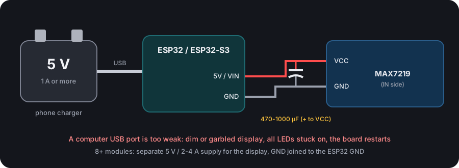
Power (read this)
Power the clock from a 5 V / 1 A (or stronger) phone charger. A computer's USB port cannot drive the display:
the LEDs stay dim, all LEDs stay on or show garbage, the board keeps restarting and drops off USB.
That was the cause of every "display does not work" case during testing; a 1 A charger fixed all of them.
Flashing from a computer is fine; test the display on the charger.
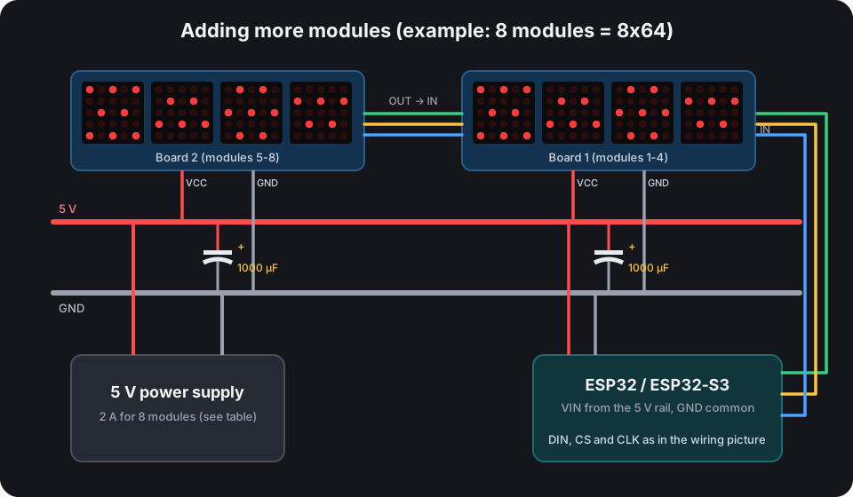
More modules and power
Connect OUT of one board to IN of the next, then set the module count in the app (Display).
Modules
Display
Supply
4
8x32
5 V / 1 A (USB is fine)
8
8x64
5 V / 2 A, separate supply
12
8x96
5 V / 3 A
16
8x128
5 V / 4 A
Above 4 modules feed 5 V to the boards directly (not through the ESP32), with a 470-1000 µF capacitor at each board.
Plug the board into the phone with a USB-OTG adapter (or a USB-C data cable).
In the app: Install firmware → Find my board → Install. The app detects ESP32 / ESP32-S3 and writes the right image (about 20-60 s).
A1. From your browser (nothing to install)
Open mtpcode.com/flash in Chrome or Edge on a computer, plug the board in, press
Install. ESP32, ESP32-S3 and ESP8266 (NodeMCU / D1 mini).
A2. From a PC (no phone, no PlatformIO)
desktop-flasher: a small program that finds the board, downloads the latest firmware and installs it
(window or command line, Windows / Linux / macOS). python desktop-flasher/dotglow_flasher.py or the .exe.
B. PlatformIO
bash
pio run -e esp32s3 -t upload --upload-port COM5     # ESP32-S3 (the "USB" port)
pio run -e esp32dev -t upload                        # classic ESP32
Full images (bootloader + partitions + app) are made by python tools/release.py.
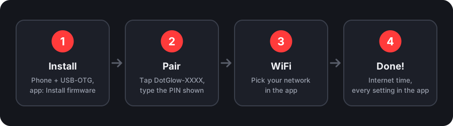
First setup
Power on. The clock plays its welcome animation and shows manoranjan.dev.
Pair. In the app tap DotGlow-XXXX. The clock shows a 6-digit PIN; type it in Android's pairing request.
WiFi. Tap Set up, pick your network, type the password. The clock restarts and fetches the time.
Done. Change anything from the app. The clock scrolls its IP address for the web page.
No app? The clock opens a WiFi hotspot DotGlow-XXXX; join it and the setup page opens (or http://192.168.4.1).
Using the clock
App: brightness, night mode, time format and zone, digit style, effects, messages, special days, display layout, updates, security.
Web page:http://<clock IP> or http://dotglow.local, with an optional login password.
BOOT button: short press = scroll the IP · double press = rotate the display 180° · hold 5 s = WiFi setup ·
hold 10 s = remove the web password.
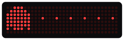
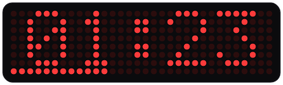
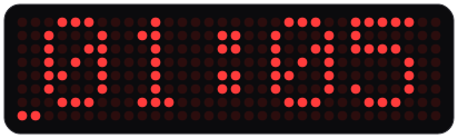
Stopwatch
On the display
Running
Paused (blinks)
After an hour
MM:SS, tenths fill the bottom row
Digits blink, time kept
HH:MM, the bottom row fills once a minute
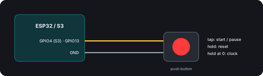
Button wiring (optional)
In the app:Stopwatch → Start / Pause / Reset / Back to the clock. The app shows a live copy of the display.
With a button (optional, from GPIO4 on the S3 / GPIO13 on the ESP32 to GND, no resistor needed):
tap = start / pause (from the clock: open the stopwatch), hold = reset, hold at 0 = back to the clock.
With 6 or more modules it shows HH:MM:SS all the time.
Updates
How
When to use
GitHub over WiFi
Automatic at night (if enabled) or Updates → Check now
App over Bluetooth
Updates → Update over Bluetooth: no WiFi needed, about 30 s
USB from the phone
New or broken boards: Install firmware
Web upload
Upload firmware.bin on the web page (password protected)
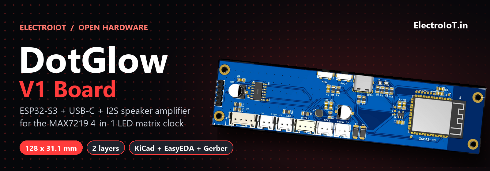
Hardware: the DotGlow V1 board
A custom 128 x 31.1 mm PCB that stacks on the back of the 4-in-1 MAX7219 module: ESP32-S3, USB-C, I2S speaker amplifier,
stopwatch / LDR / DHT22 connectors, and an I2C port for a clock chip. Schematic, Gerbers, BOM, 3D renders and the
KiCad / EasyEDA files are in hardware/pcb/. Untested V1. ▶ Watch the PCB Short.
Troubleshooting
Problem
Fix
Board light is on but the app doesn't see the clock
Join the grounds: display GND, board GND and the power supply GND must be connected together. Use a stable 5 V supply: a weak one restarts the board when Bluetooth starts
Dim, all LEDs stuck on, or garbage
Power: use a 5 V / 1 A charger, not a computer USB port; add the capacitor
Only the first module works
A broken link between modules (re-solder the joints between module 1 and 2)
ESP32 doesn't start after wiring
A wire is on CMD / SD0-SD3 / CLK (flash pins): move it
Text scrambled / mirrored
App → Display → module type / mirror / flip
Upside down
App → Display → Rotate 180°, the rotate button on the dashboard, or double-press BOOT
Keeps restarting
Better 5 V supply, add the capacitor; after 3 crashes it starts in safe mode
Can't pair
Use the PIN on the display (not 0000 / 1234). After a factory reset the app re-pairs by itself
"Getting time..." forever
WiFi has no internet, or the time zone is wrong (App → Clock & time)
Board drops off USB / flash stops half way
Take the display's 5 V wire off the board while flashing (the display draws more than USB gives); short thick data cable, another port
USB install fails
Use a data cable; hold BOOT, tap RESET, release BOOT, try again
The code is MIT licensed, but the DotGlow name, logo and app icon are not covered by the licence.
Forks and rebuilt apps are welcome; please publish them under your own name, icon and package
(not com.electroiot.dotglow), so users can tell them apart from the official app.
It measures 128 × 33 mm and has 2 copper layers, 1.6 mm thick.
What parts does the Dotglow v1 use?
41 parts, built around the 74AHCT125D, ESP32-S3-WROOM-1-N16R8, DHT22 and USBLC6-2SC6. The full list of its parts is on this page, with links to each part's symbol and footprint where PCBKit's library has them.
Where can I download the Dotglow v1 KiCad files?
From the ElectroIoT/DotGlow-ESP32 repository on GitHub, at the commit this page was made from: the board is hardware/pcb/kicad/dotglow-v1.kicad_pcb and its schematic hardware/pcb/kicad/dotglow-v1.kicad_sch. PCBKit opens the board in the browser, with nothing to install.
Can I use the Dotglow v1 design in my own project?
Its repository publishes it under the MIT licence: you may reuse it on that licence's terms (keep the author's notice, and for a copyleft licence share your changes alike).
A pocket-size Morse key. One button, one RGB LED, an ESP32-S3, and a battery. Plug it in over USB-C or pair it over Bluetooth and it types Morse into any device as a standard keyboard. Fully open, down to the copper.