4 layers50 × 65 mm
FeroFlyF405
Ozonised/FeroFlyF405
FeroFlyF405 an open source STM32F405 based flight controller running INAV
150 parts44CERN-OHL-P-2.0
 Electro707/addressable_led_controller
An addressable LED controller
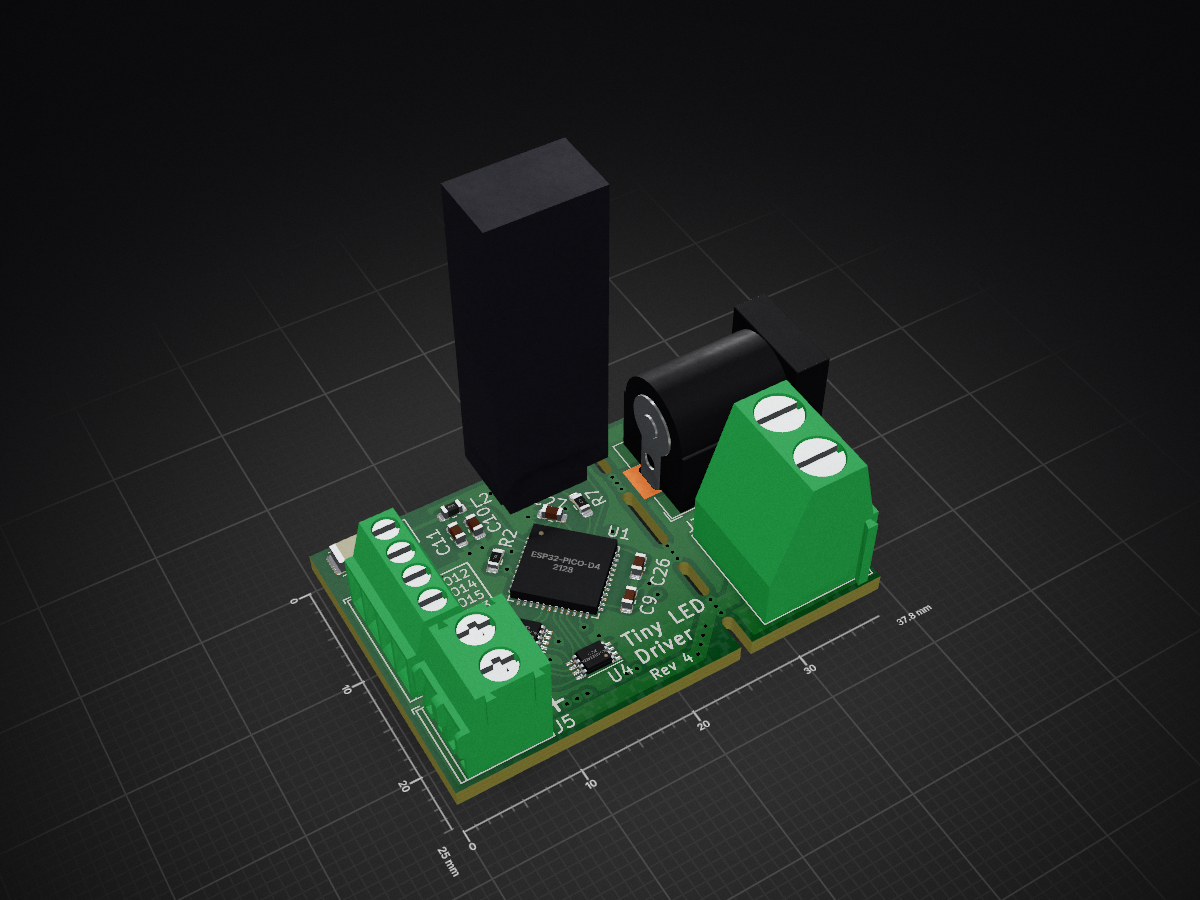
LED Controller is an open-source printed circuit board by Electro707, from the Electro707/addressable_led_controller repository on GitHub, published under the GPL-3.0 licence. It is a 4-layer board of 37.8 × 25 mm with 35 parts on 57 nets, routed with 211 tracks and 43 vias.
It is built around the ESP32-PICO-D4, AP62200WU-7-52 and 74LVCH2T45DC, with the SMF15A and SP0505BAHTG among its other parts. Its parts include 12 capacitors, 5 resistors, 5 ICs, 5 connectors and 3 inductors. It belongs with the ESP32 and RISC-V boards of this library.


This is the repository for my LED strip controller. This LED controller is capable of controlling any addressable LED strip (1 or two data wires).
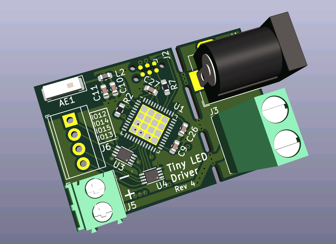
Image of real PCB Rev4 coming soon!
This controller uses the WLED firmware. Instructions to upload the firmware unto the board can be found on their webpage.
Thru J2, you can connect an ESP32 programmer such as the ESP-Prog. You can also make your own "automatic downloader" (i.e not requiring to reset the device and selecting boot mode when uploading) circuit. Details of which can be found on Espressif's ESP-Prog docs on Automatic Downloading Function.
The PI Matching network values have been calculated by measuring the impedance of the antenna mounted on a bare board. As image of the setup is shown below:
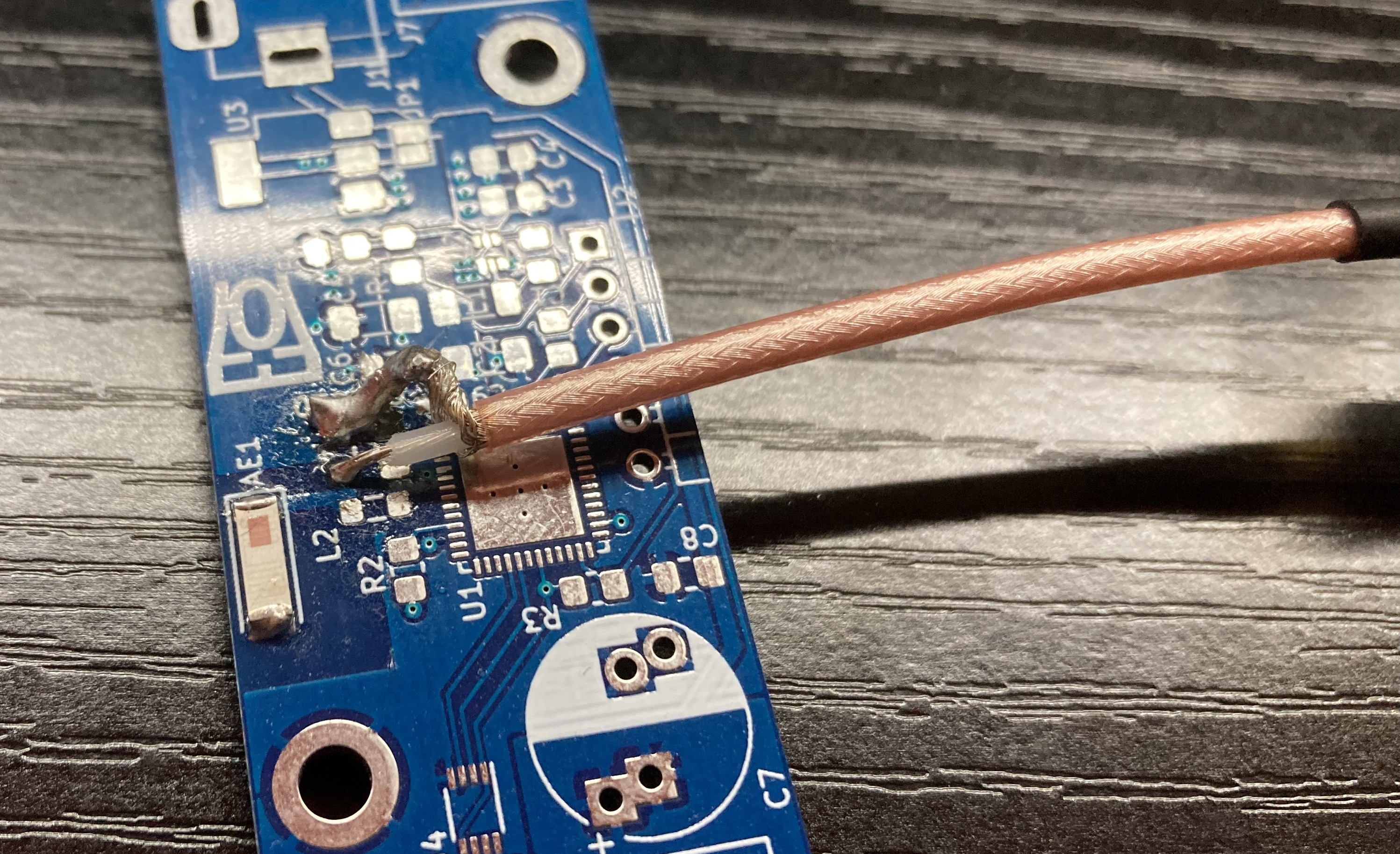
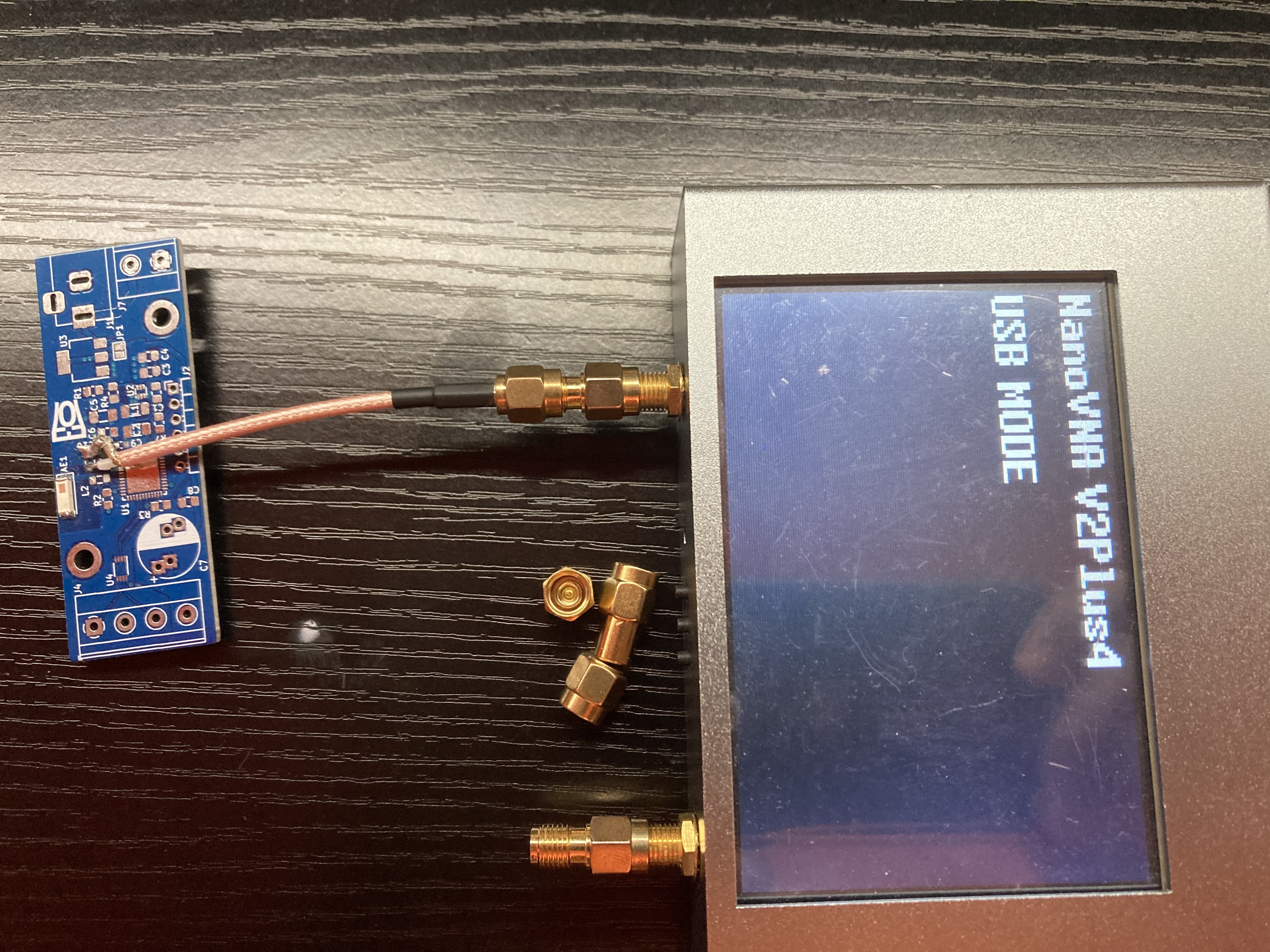
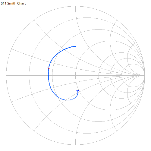
The impedance was measured with my handy NanoVNA V2+4. The measured impedance at 2.45Ghz, shown below, was 21.9+5.48jΩ. Plugging those numbers into a PI matching network calculator, we get 2.09nH for L, 2.65pF for Cs, and 3.99pF for Cl. The values have been rounded to the nearest available values that is reasonable to buy (this is RF anyways, I could have sneezed and the values would be slightly off).
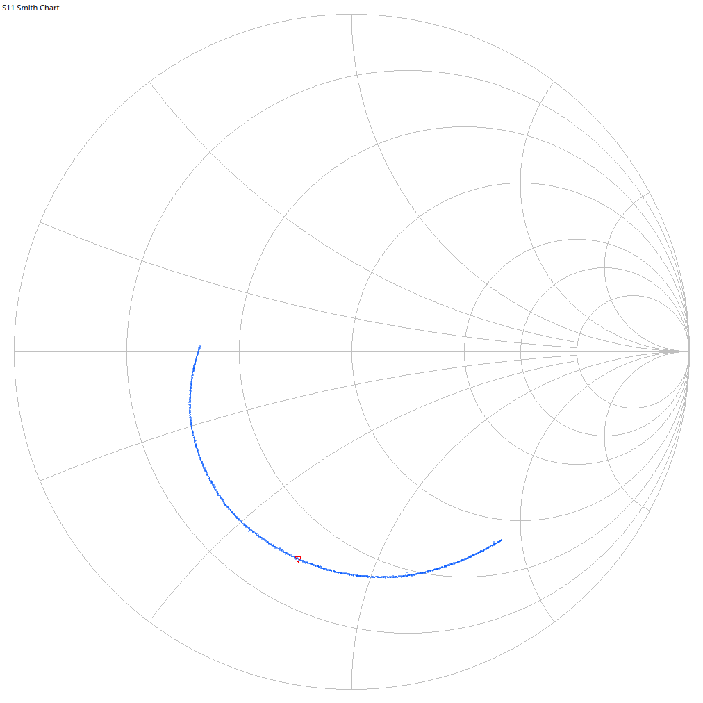
At 2.45Gz, impedance was 17.5-35.8jΩ. We get 2.3194nH for L, 3.898pF for Cs, and 4.429pF for Cl.
Rev 3 of this project was a fully-featured POE version of this controller. I since has made this revision, which is closer to the original small design, so I decided to branch Rev3 off to it's own repo: Electro707/addressable_led_controller_poe
Over at DesignConsiderations.md, I wrote some design reasonings as to why some things are the way they are designed for Rev 4 of the board. Feel free to have a look, keep in mind they are more internal notes if anything.
| Qty | Value | Footprint | References |
|---|---|---|---|
| 4 | 0.1u | Capacitor_SMD:C_0603_1608Metric | C9, C17, C26, C27 |
| 4 | 0.1uF | Capacitor_SMD:C_0603_1608Metric | C1, C2, C6, C8 |
| 2 | 10k | Resistor_SMD:R_0603_1608Metric | R2, R3 |
| 2 | 22uF | Capacitor_SMD:C_1206_3216Metric_Pad1.33x1.80mm_HandSolder | C3, C5 |
| 2 | 74LVCH2T45DC | Package_SO:VSSOP-8_2.3x2mm_P0.5mm | U3, U4 |
| 1 | 10k | Resistor_SMD:R_0805_2012Metric_Pad1.20x1.40mm_HandSolder | R4 |
| 1 | 2.2nH | Inductor_SMD:L_0603_1608Metric | L2 |
| 1 | 2.2pF | Capacitor_SMD:C_0603_1608Metric | C10 |
| 1 | 3.3uH | Inductor_SMD:L_1206_3216Metric_Pad1.22x1.90mm_HandSolder | L3 |
| 1 | 31.6k | Resistor_SMD:R_0805_2012Metric_Pad1.20x1.40mm_HandSolder | R1 |
| 1 | 470 | Resistor_SMD:R_0603_1608Metric_Pad0.98x0.95mm_HandSolder | R7 |
| 1 | 4pF | Capacitor_SMD:C_0603_1608Metric | C11 |
| 1 | AP62200WU-7 | Package_TO_SOT_SMD:TSOT-23-6 | U2 |
| 1 | Antenna_Chip | RF_Antenna:Johanson_2450AT43F0100 | AE1 |
| 1 | Barrel_Jack | Connector_BarrelJack:BarrelJack_Horizontal | J1 |
| 1 | Conn_01x06_Female | Connector:Tag-Connect_TC2030-IDC-NL_2x03_P1.27mm_Vertical | J2 |
| 1 | ESP32-PICO-D4 | Package_DFN_QFN:QFN-48-1EP_7x7mm_P0.5mm_EP5.3x5.3mm | U1 |
| 1 | Jumper_2_Bridged | Jumper:SolderJumper-2_P1.3mm_Open_TrianglePad1.0x1.5mm | JP1 |
| 1 | L_Ferrite | Inductor_SMD:L_0805_2012Metric | L1 |
| 1 | MCP1792x-5002xCB | Package_TO_SOT_SMD:SOT-23 | U5 |
| 1 | Polyfuse | Fuse:Fuse_1206_3216Metric | F1 |
| 1 | SMF15A | Diode_SMD:D_SMF | D1 |
| 1 | SP0505BAHT | Package_TO_SOT_SMD:SOT-23-6 | D2 |
| 1 | Screw_Terminal_01x02 | TerminalBlock_Phoenix:TerminalBlock_Phoenix_PT-1,5-2-3.5-H_1x02_P3.50mm_Horizontal | J5 |
| 1 | Screw_Terminal_01x02 | TerminalBlock_Phoenix:TerminalBlock_Phoenix_MKDS-1,5-2-5.08_1x02_P5.08mm_Horizontal | J3 |
| 1 | Screw_Terminal_01x04 | TerminalBlock_TE-Connectivity:TerminalBlock_TE_282834-4_1x04_P2.54mm_Horizontal | J6 |
It measures 37.8 × 25 mm and has 4 copper layers, 1.61 mm thick.
35 parts, built around the ESP32-PICO-D4, AP62200WU-7-52, 74LVCH2T45DC and SMF15A. The full list of its parts is on this page, with links to each part's symbol and footprint where PCBKit's library has them.
From the Electro707/addressable_led_controller repository on GitHub, at the commit this page was made from: the board is PCB/LED_Controller.kicad_pcb and its schematic PCB/LED_Controller.kicad_sch. PCBKit opens the board in the browser, with nothing to install.
Its repository publishes it under the GPL-3.0 licence: you may reuse it on that licence's terms (keep the author's notice, and for a copyleft licence share your changes alike).
Ozonised/FeroFlyF405
FeroFlyF405 an open source STM32F405 based flight controller running INAV


AllenNeuralDynamics/harp.device.lickety-split
0360: an ephys-compliant capacitive lick detector

AllenNeuralDynamics/harp.device.treadmill-driver
0326: a Harp-compatible device for controlling an instrumented mouse treadmill

AllenNeuralDynamics/harp.device.sniff-detector
0382: Signal conditioning board for an implanted thermistor


MohamedAlDeep/RGB-Mechanical-KEEB-
This is my custom made 75% rgb mechanical keyboard

r3dpath/RpiFly_Hardware
While most of the functionality here has been tested to work theres certainally some marginal design decisions, just beware.