2 layers
Nrf bga
github-linguist/linguist
Language Savant. If your repository's language is being reported incorrectly, send us a pull request!
12 parts14kMIT

 electricant/T10-W5W-LED-Replacement
KiCad design for a T10 (W5W) 12V bulb replacement using LEDs
T10 LED lamp is an open-source printed circuit board by electricant, from the electricant/T10-W5W-LED-Replacement repository on GitHub, published under the Unlicense licence. It is a 2-layer board of 10 × 26 mm with 12 parts on 11 nets, routed with 33 tracks and 27 vias.
Its parts include 2 capacitors, 2 diodes, 1 resistor and 1 IC. It belongs with the lEDs and displays boards of this library.
KiCad design for a T10 (W5W) 12V bulb replacement using LEDs, reducing power consumption and providing a longer lifespan compared to traditional filament bulbs.
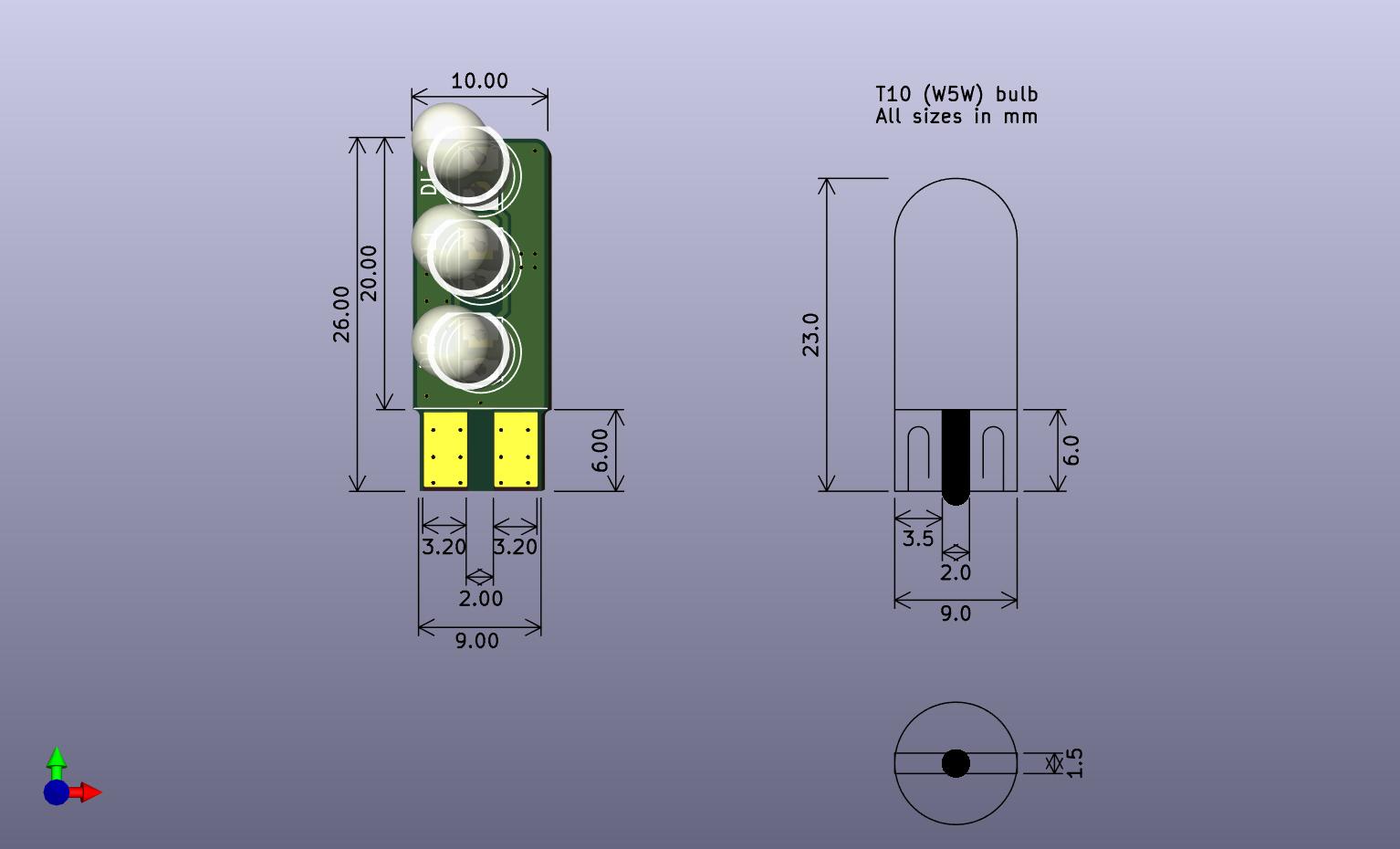
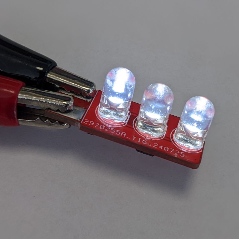
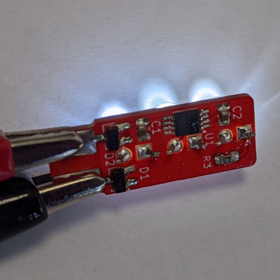
The goal is to create a more energy-efficient, long-lasting LED alternative to traditional filament bulbs commonly used in automotive applications.
The LEDs are driven by the LT1962 voltage regulator, acting as a constant current source for stable LED operation. The LT1962 is a low-dropout (LDO) linear voltage regulator with the following key features that make it particularly suitable for this application:
A series resistor (R3 in the schematic) is used to set the current flowing through the LEDs in conjunction with the LT1962 voltage regulator. The LT1962 regulates the voltage to a specific reference value (1.22V for the adjustable version, or fixed values such as 1.5V, 1.8V, etc., depending on the version used).
The value of the series resistor $R_3$ can be calculated using the following formula:
$$ R_3 = \frac{V_{ref}}{I_{LED}} $$
Where:
It's important to ensure that the total voltage drop across the LED and the resistor remains below 12V to maintain constant current operation. If the LED's forward voltage is too high, or if the input voltage is too low, the LT1962 might not regulate properly, leading to variations in the LED current.
If you are using the adjustable version of the LT1962 with a reference voltage $V_{ref}$ of 1.22V and you want to set the LED current $I_{LED}$ to 20mA, the resistor value would be:
$$ R_3 = \frac{1.22V}{0.02A} = 61 \Omega $$
Rounded to the nearest standard value, you would use a 62Ω resistor to achieve approximately a 19.7mA current through the LED.
Contributions are welcome! Feel free to fork this repository and submit a pull request with your improvements.
| Qty | Value | Footprint | References |
|---|---|---|---|
| 3 | LED | LED_SMD:LED_PLCC-2_3.4x3.0mm_KA | DL4, DL5, DL6 |
| 3 | LED | LED_THT:LED_D5.0mm_Clear | DL1, DL2, DL3 |
| 2 | 4.7u | Capacitor_SMD:C_0805_2012Metric | C1, C2 |
| 2 | BAV99 / BAT54S | Package_TO_SOT_SMD:SOT-23_Handsoldering | D1, D2 |
| 1 | 120 | Resistor_SMD:R_0805_2012Metric_Pad1.20x1.40mm_HandSolder | R3 |
| 1 | LT1962 | Package_SO:MSOP-8_3x3mm_P0.65mm | U1 |
github-linguist/linguist
Language Savant. If your repository's language is being reported incorrectly, send us a pull request!


google/mozc-devices
Circuit diagrams and firmware source code for Gboard DIY keyboards


hackclub/OnBoard
💡 Join 1,000 teenagers and make your first PCB with a $100 grant!

VoronDesign/Voron-Tap
Tap is a nozzle-based z-probe for the V2 and Trident printer designs. The entire toolhead moves to trigger an optical switch. Tap offers many advantages:

stacksmashing/pico-tpmsniffer
A simple, very experimental TPM sniffer for LPC bus
It measures 10 × 26 mm and has 2 copper layers, 1.6 mm thick.
12 parts. The full list of its parts is on this page, with links to each part's symbol and footprint where PCBKit's library has them.
From the electricant/T10-W5W-LED-Replacement repository on GitHub, at the commit this page was made from: the board is T10_LED_lamp.kicad_pcb and its schematic T10_LED_lamp.kicad_sch. PCBKit opens the board in the browser, with nothing to install.
Its repository publishes it under the Unlicense licence: you may reuse it on that licence's terms (keep the author's notice, and for a copyleft licence share your changes alike).