Skip to the content
PCBKitNew board
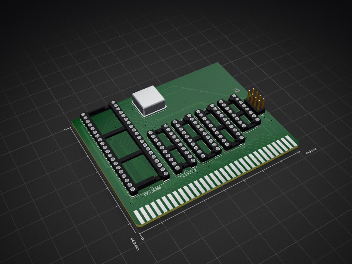
2 layers81.2 × 64.8 mmCPU, the printed circuit board in 3D

WARNING! These boards are still very early models and likely contain bugs. They've been observed to work with either no modification or with minor modification (like adding a pullup resistor) during the soldering stage…

Size
81.2 × 64.8 mm
Copper layers
2
Thickness
1.6 mm
Parts
9
Nets
90
Pads
192
Tracks, vias
789, 48
Pours
1
Routed
Yes
KiCad
KiCad 5 (file 20171130)
Created
5 Dec 2021
Updated
21 Aug 2022

Overview

CPU is an open-source printed circuit board by eigenco, from the eigenco/PCB repository on GitHub. It is a 2-layer board of 81.2 × 64.8 mm with 9 parts on 90 nets, routed with 789 tracks and 48 vias.

It is built around the ACH-14.31818MHZ-EK. Its parts include 2 connectors and 1 resistor.

Main components

1

README

README.md

PCB

WARNING! These boards are still very early models and likely contain bugs. They've been observed to work with either no modification or with minor modification (like adding a pullup resistor) during the soldering stage, but be aware that they might not work directly "out of the box" for you or present a risk of something breaking.

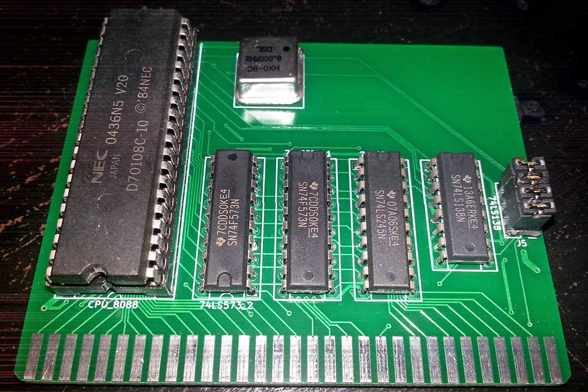
Minimal 8088 8 bit ISA board

This board is slightly custom. Signals INTAK and INT have been routed through DRQ2 and DACK2 to allow external PIC-board in the BUS, equally HLDA and HOLD have been routed through DRQ3 and DACK3 to allow external DMAC-board in the BUS. These customizations mean that DMA channels 2 and 3 cannot be used normally. The board will boot when RESET jumper is connected being initially disconnected during power-up. There are 3 other jumpers for allowing operation with or without PIC and DMAC. Can boot into DOS with suitable BIOS (v2). Tested with 8 MHz V20.
CPU

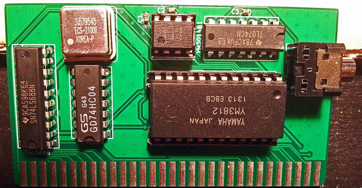
Minimal Adlib compatible 8 bit ISA board

This board has its own oscillator and thus requires neither CLK or OSC to be present in the BUS.
OPL2

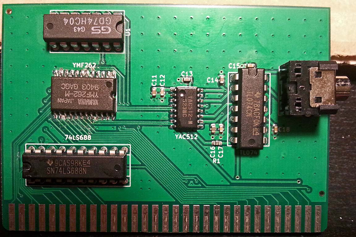
Minimal OPL3 compatible 8 bit ISA board

This board requires OSC (14.31818 MHz) signal present in the BUS.
OPL3

Minimal 512 KB 8 bit ISA RAM board

This board is configured to occupy 0x00000-0x7FFFF.
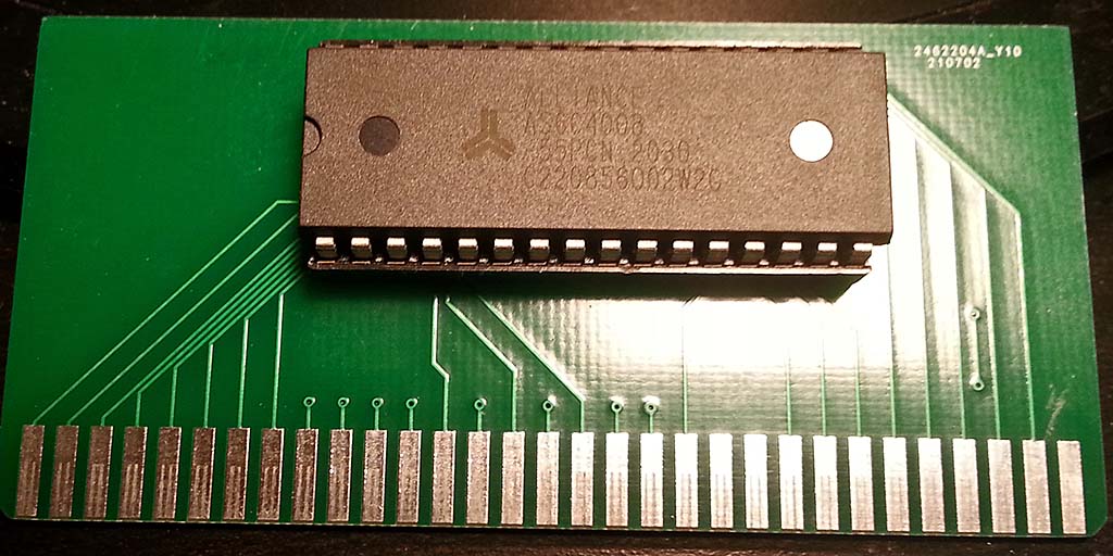
MEM

Control 8 bit ISA devices through passive backplane using Raspberry Pi (14.31818 MHz oscillator is included, MEMW/MEMR/IOW/IOR are supported, no IRQ or DMA)
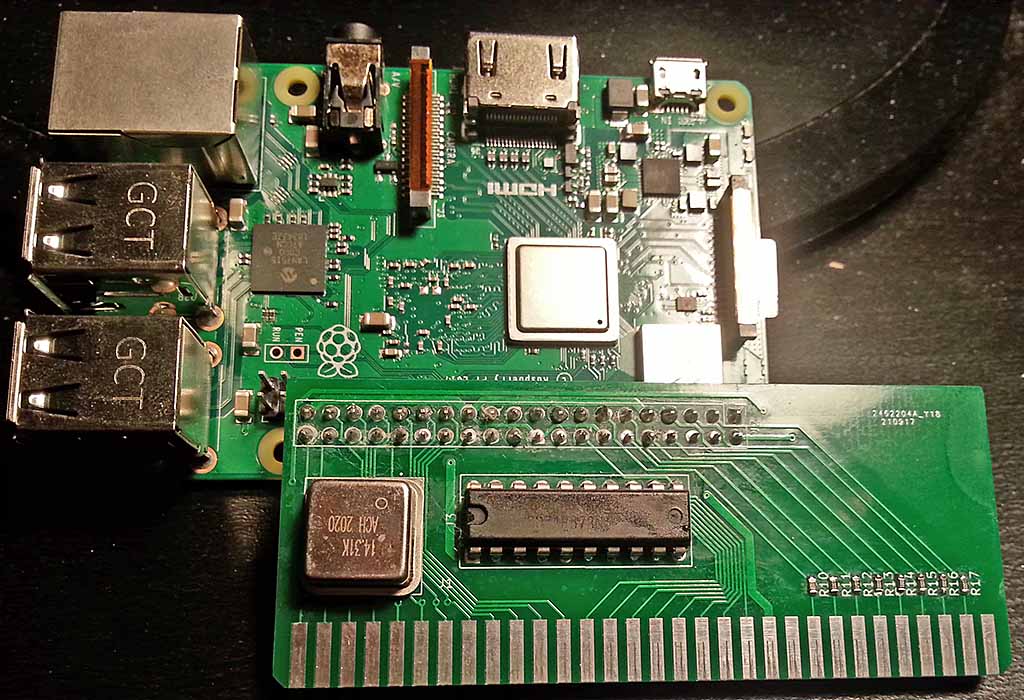
RPI2ISA

Board with 8259 Programmable Interrupt Controller and 8254 Programmable Interval Timer (there is wrong 74LS93 chip in place of 74LS92 in the picture as I didn't have the correct chip at the moment of testing, 74LS93 is decade divider whereas this board requires octal divider so the PIT ran at slightly lower frequence in this test than normally).
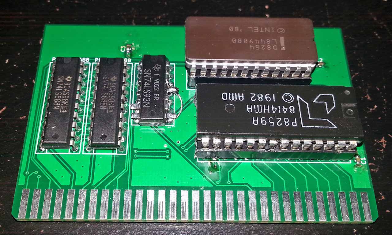
pic

Example of "everything" in a backplane, early video https://www.youtube.com/watch?v=vcOmHcExV3M
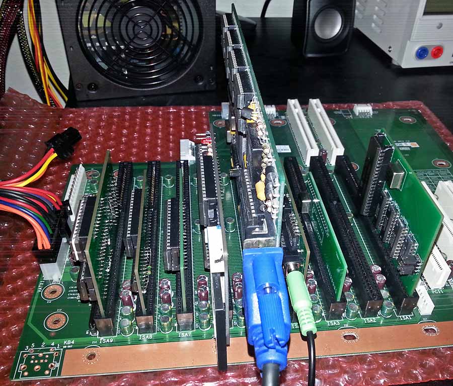
bp

Parts

9
QtyValueFootprintReferences
3Conn_02x10_Counter_ClockwisePackage_DIP:DIP-20_W7.62mm_Socket74LS245, 74LS573_1, 74LS573_2
11kResistor_SMD:R_0603_1608MetricR1
1ACH-14.31818MHZ-EKSamacSys_Parts:ACH16000MHZEKCLK8
1Bus_ISA_8bitadlib:BUS_PCJ4
1Conn_02x04_Odd_EvenConnector_PinHeader_2.54mm:PinHeader_2x04_P2.54mm_VerticalJ5
1Conn_02x08_Counter_ClockwisePackage_DIP:DIP-16_W7.62mm_Socket74LS138
1Conn_02x20_Counter_ClockwisePackage_DIP:DIP-40_W15.24mm_Socket_LongPadsCPU_8088

Questions

How big is the CPU PCB?

It measures 81.2 × 64.8 mm and has 2 copper layers, 1.6 mm thick.

What parts does the CPU use?

9 parts, built around the ACH-14.31818MHZ-EK. The full list of its parts is on this page, with links to each part's symbol and footprint where PCBKit's library has them.

Where can I download the CPU KiCad files?

From the eigenco/PCB repository on GitHub, at the commit this page was made from: the board is CPU8088/CPU.kicad_pcb. PCBKit opens the board in the browser, with nothing to install.

Can I use the CPU design in my own project?

Its repository states no licence, so its author keeps all rights: ask eigenco before reusing the design.

More from eigenco/PCB

3
  • 2 layers81.2 × 56.3 mmOPL3, the printed circuit board in 3D

    OPL3

    eigenco/PCB

    WARNING! These boards are still very early models and likely contain bugs. They've been observed to work with either no modification or with minor modification (like adding a pullup resistor) during the soldering stage…

    16 parts5
  • 2 layers81.2 × 45.8 mmOPL2, the printed circuit board in 3D

    OPL2

    eigenco/PCB

    WARNING! These boards are still very early models and likely contain bugs. They've been observed to work with either no modification or with minor modification (like adding a pullup resistor) during the soldering stage…

    11 parts5
  • 2 layers81.2 × 53.8 mmPICPIT, the printed circuit board in 3D

    PICPIT

    eigenco/PCB

    WARNING! These boards are still very early models and likely contain bugs. They've been observed to work with either no modification or with minor modification (like adding a pullup resistor) during the soldering stage…

    9 parts5

Similar boards

  • 2 layers81.3 × 33.8 mmISARPiv2, the printed circuit board in 3D

    ISARPiv2

    eigenco/RPiISA

    Raspberry Pi to ISA bus, including Adlib emulation and PCB (KiCad)

    12 parts48
  • 4 layers84.3 × 108.4 mmUBITz Host z80-Host, the printed circuit board in 3D

    UBITz Host z80-Host

    dumaiss/uBITz

    **μBITz** – *ZAP 80s dreams into silicon.* Open modular 8-bit system: dock Z80/6502, tile SID/POKEY, boot in '83. M.2 LVDS serial, I²C map, Parity-10, ZAP IRQs. Spec + KiCad + Verilog + ref impl. Build. ZAP.

    50 parts
  • 2 layers103 × 30.5 mmTS Back Endcap, the printed circuit board in 3D

    TS Back Endcap

    EEVengers/ThunderScope

    ThunderScope GitHub Repo

    9 parts1.3kMIT
  • 2 layers31.8 × 47.6 mmNGC 38 connector, the printed circuit board in 3D

    NGC 38 connector

    rusefi/rusefi

    rusefi - GPL internal combustion engine control unit

    9 parts1.2k
  • 2 layers24 × 27.3 mmExpansion Card Retrofit, the printed circuit board in 3D

    Expansion Card Retrofit

    FrameworkComputer/ExpansionCards

    Reference designs and documentation to create Expansion Cards for the Framework Laptop

    9 parts1.1kCC-BY-4.0
  • 2 layers15.6 × 17.3 mmSKR Mini TFT Thermistor Board, the printed circuit board in 3D

    SKR Mini TFT Thermistor Board

    VoronDesign/Voron-Hardware

    Cool Hardware designed by the Voron Design group

    9 parts1.1kGPL-3.0
  • 2 layers39.1 × 49.5 mmLearnoliver, the printed circuit board in 3D

    Learnoliver

    hackclub/OnBoard

    💡 Join 1,000 teenagers and make your first PCB with a $100 grant!

    9 parts915
  • 2 layers17.4 × 16.9 mmToolhead, the printed circuit board in 3D

    Toolhead

    tanaes/whopping_Voron_mods

    9 parts787GPL-3.0