2 layers75 × 100 mm
Phased
Neumi/open_echo
Open Source echo sounder / depth sounder / SONAR for bathymetry and research. Arduino based and compatible.
77 parts530

 eggsworks/tamago6039
A semi-split, ortho, low-profile keyboard featuring a joystick
Tamago60 is an open-source printed circuit board by eggsworks, from the eggsworks/tamago60 repository on GitHub, published under the GPL-3.0 licence. It is a 2-layer board of 275.3 × 99.8 mm with 77 parts on 88 nets, routed with 667 tracks and 96 vias.
Its parts include 62 switches, 2 resistors, 1 IC, 1 diode and 1 connector. It belongs with the keyboards and input boards and the AVR (ATmega, ATtiny) boards of this library.
tamago60 is a hotswap, semi-split, low profile, ortholinear keyboard with a joystick in the middle.
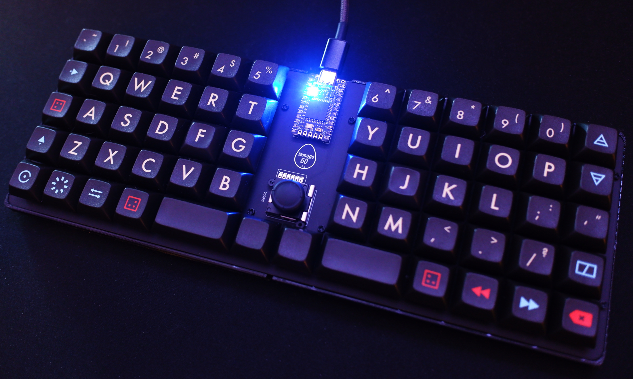
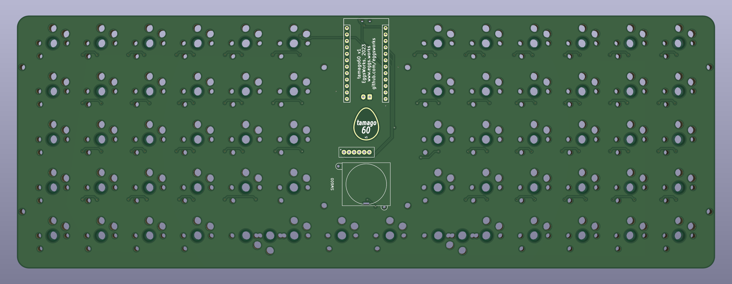
PCB prototyping for the tamago60 was kindly sponsored by PCBWay. If you choose to build your own tamago60, consider ordering from PCBWay to experience their fast turnaround, high quality production, and excellent customer service. Thanks, PCBWay!
I've also shared this design on their site to make it really easy to order your own board:

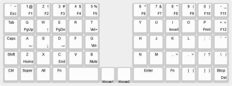
We all love those laptops with the trackpoint in the middle of the keyboard, right? Influenced by that design, with an ergo twist and a healthy dose of minimalism, the tamago60 is a roughly-60% board with a joystick stuck between two semi-split ortho halves.
This design uses MX spacing (19mm) to allow flexibility with choice of keycaps. For the same reason, switches are installed directly to the PCB rather than into a switchplate (DSA keycaps will crash into the plate if used with Choc V2's).
A wireless build of this board has not yet been validated, but there are some features intended to improve quality-of-life for any users who wish to try.
Prepare the back of the board with paste and place the SMT components:
If you choose not to install the two resistors, you can simply bridge the pads intended for each.
Select two pads to bridge on the jumper near the joystick to choose whether the press action should be a left or right click (it shares a position in the matrix with one of the keyswitches below it).
Use your preferred heating method to reflow, then move on to the THT components on the front of the board:
That's all there is to it! Install your switches and keycaps, flash the firmware, and your board is ready to use.
Firmware is available from our fork of QMK.
Model files for a 3D-printable case are available in this repo. The case is split in two parts in order to fit most beds. A cavity is provided in order to install a battery in the case of a wireless build.
Install 8 M2 brass inserts in each half in order to mount the PCB to the case.
This repository is available under the terms of the GPL, verison 3.
Some portions are derived from:
| Qty | Value | Footprint | References |
|---|---|---|---|
| 58 | switch_with_diode | tamago60:Choc_Hotswap | SW101, SW102, SW103, SW104, SW105, SW106, SW107, SW108, SW109, SW110, SW111, SW112, SW201, SW202, SW203, SW204 +42 |
| 8 | MountingHole | MountingHole:MountingHole_2.2mm_M2 | H1, H2, H3, H4, H5, H6, H7, H8 |
| 2 | R | Resistor_SMD:R_1206_3216Metric | R1, R2 |
| 1 | Conn_01x02_Female | Connector_JST:JST_PH_S2B-PH-K_1x02_P2.00mm_Horizontal | J1 |
| 1 | D | Diode_SMD:D_SOD-123 | D600 |
| 1 | JP19 | tamago60:JP19 | SW600 |
| 1 | Pro_Micro | tamago60:ProMicro | U1 |
| 1 | SW_SPDT | Button_Switch_SMD:SW_SPDT_PCM12 | SW1 |
| 1 | SolderJumper_3_Open | Jumper:SolderJumper-3_P1.3mm_Open_Pad1.0x1.5mm_NumberLabels | JP1 |
| 1 | switch_with_diode | tamago60:Choc_Hotswap_2u_left | SW505 |
| 1 | switch_with_diode | tamago60:Choc_Hotswap_2u_right | SW508 |
The 76 most common of 77 parts.
It measures 275.3 × 99.8 mm and has 2 copper layers, 1.6 mm thick.
77 parts. The full list of its parts is on this page, with links to each part's symbol and footprint where PCBKit's library has them.
From the eggsworks/tamago60 repository on GitHub, at the commit this page was made from: the board is tamago60/tamago60.kicad_pcb and its schematic tamago60/tamago60.kicad_sch. PCBKit opens the board in the browser, with nothing to install.
Its repository publishes it under the GPL-3.0 licence: you may reuse it on that licence's terms (keep the author's notice, and for a copyleft licence share your changes alike).
Neumi/open_echo
Open Source echo sounder / depth sounder / SONAR for bathymetry and research. Arduino based and compatible.

zynthian/zynthian-hw
Zynthian hardware stuff: PCBs, schemes, parts specifications, pin assignment, ...

shmoergh/hog
Fully analog two-voice monophonic synth for live performances

osiweb/unified_retro_keyboard
Project to provide keyboard replacements for various classic computers, as well as classic ASCII keyboard


AnthonyDiGirolamo/teensy-thumb-keyboard
Handheld tactile switch keyboard for Teensy 3.2 compatible boards.

