2 layers308.7 × 241.8 mm
OTTOtact
cester-ino/OTTO-hardware
those specs refer to the tactile buttons version, but a led backlight button version is in the works too.
229 parts49GPL-3.0

 EE403-CapStone/Power
Design files of power
403 charger v2 is an open-source printed circuit board by EE403-CapStone, from the EE403-CapStone/Power repository on GitHub. It is a 2-layer board of 41.8 × 31.8 mm with 23 parts on 24 nets, routed with 118 tracks and 7 vias.
It is built around the MT3608, FS312F-G and FS8205. Its parts include 7 resistors, 4 capacitors, 3 ICs, 3 diodes and 3 connectors. It belongs with the power boards of this library.

This part illustrates the design of the power associated with the project. There are two KiCAD project folders. One of them is "403_charger_v1," and another one is "403_charger_v2". "403_charger_v1" is the initial design of the power, but it has some problems with the design. "403_charger_v2" is the design that problems got corrected. In the description of the documents, "403_charger_v2" will be described.
In the KiCAD project folder, there are three main files, which are "403_charger_v2.kicad_pcb", "403_charger_v2.kicad_pro", "403_charger_v2.kicad_sch". "403_charger_v2.kicad_pcb" is the PCB file of the power. "403_charger_v2.kicad_pro" is the project file of the power. "403_charger_v2.kicad_sch" is the schematic file of the power. These three files can only be opened by the KiCAD.
 |
|---|
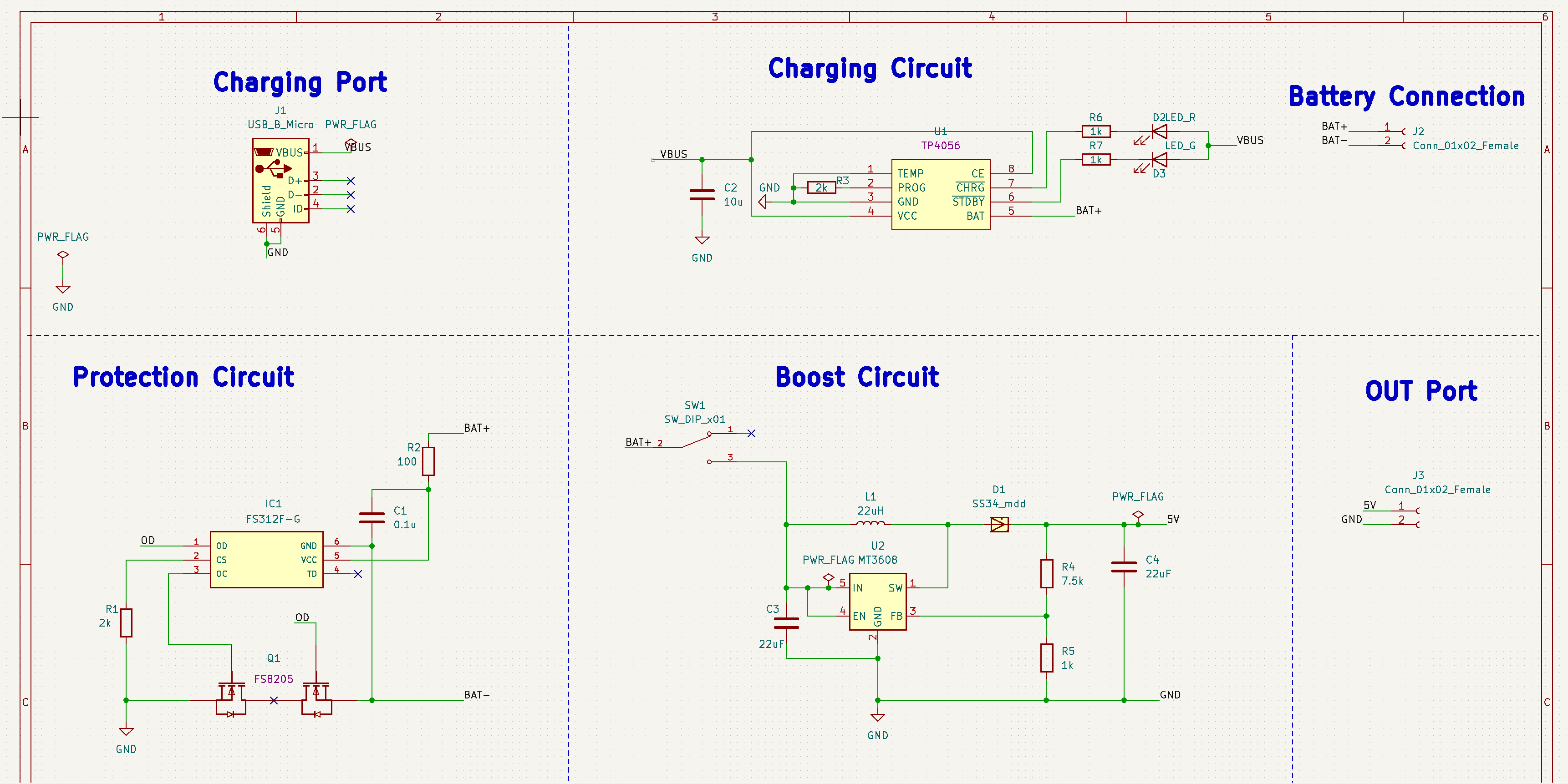
| Schematic Preview of the Power |
The circuit consists of 3 main circuits: the charging circuit, the protection circuit, and the boost circuit. Details of all components in the schematic will be shown below.
 |  |
|---|---|
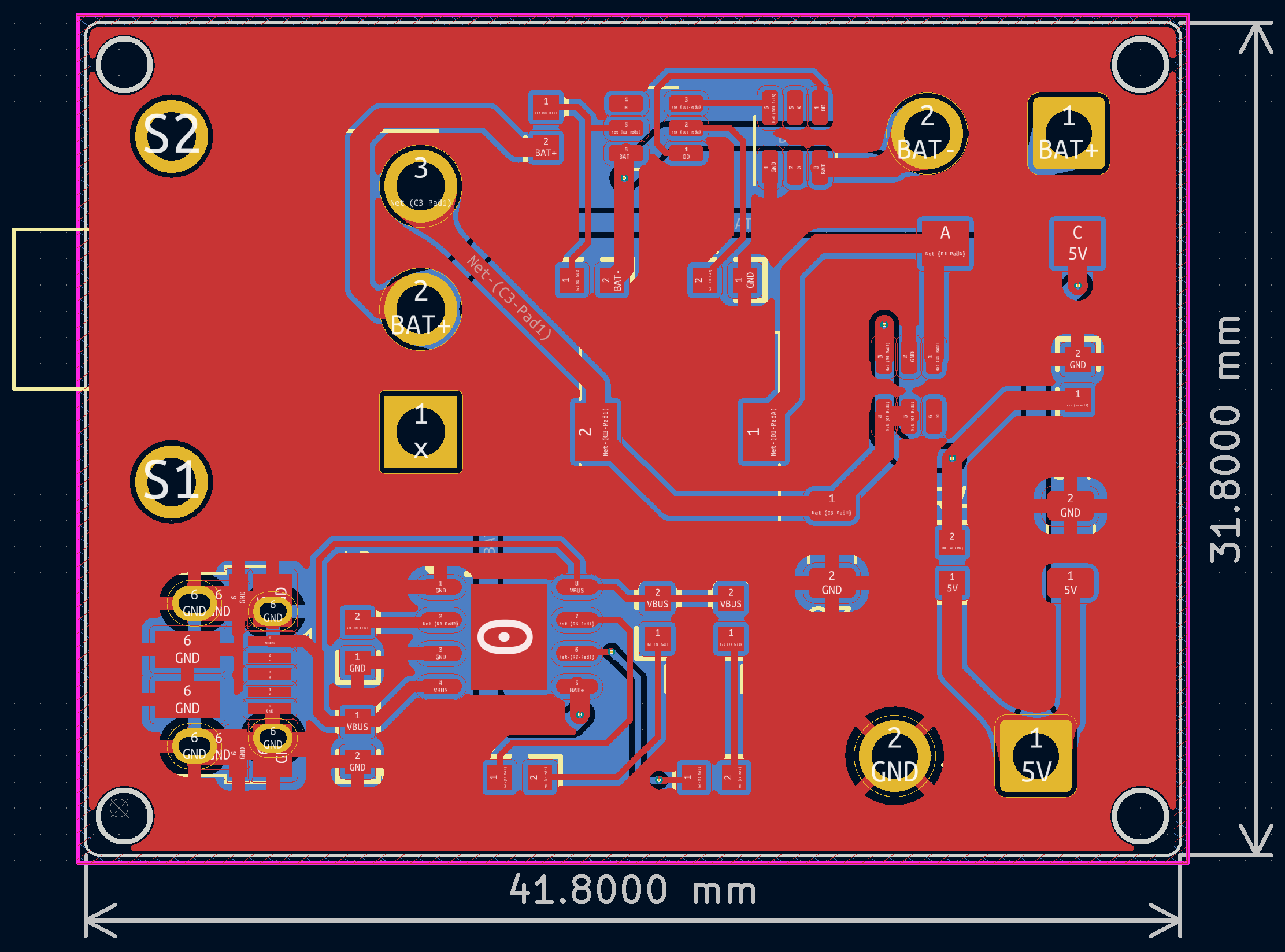
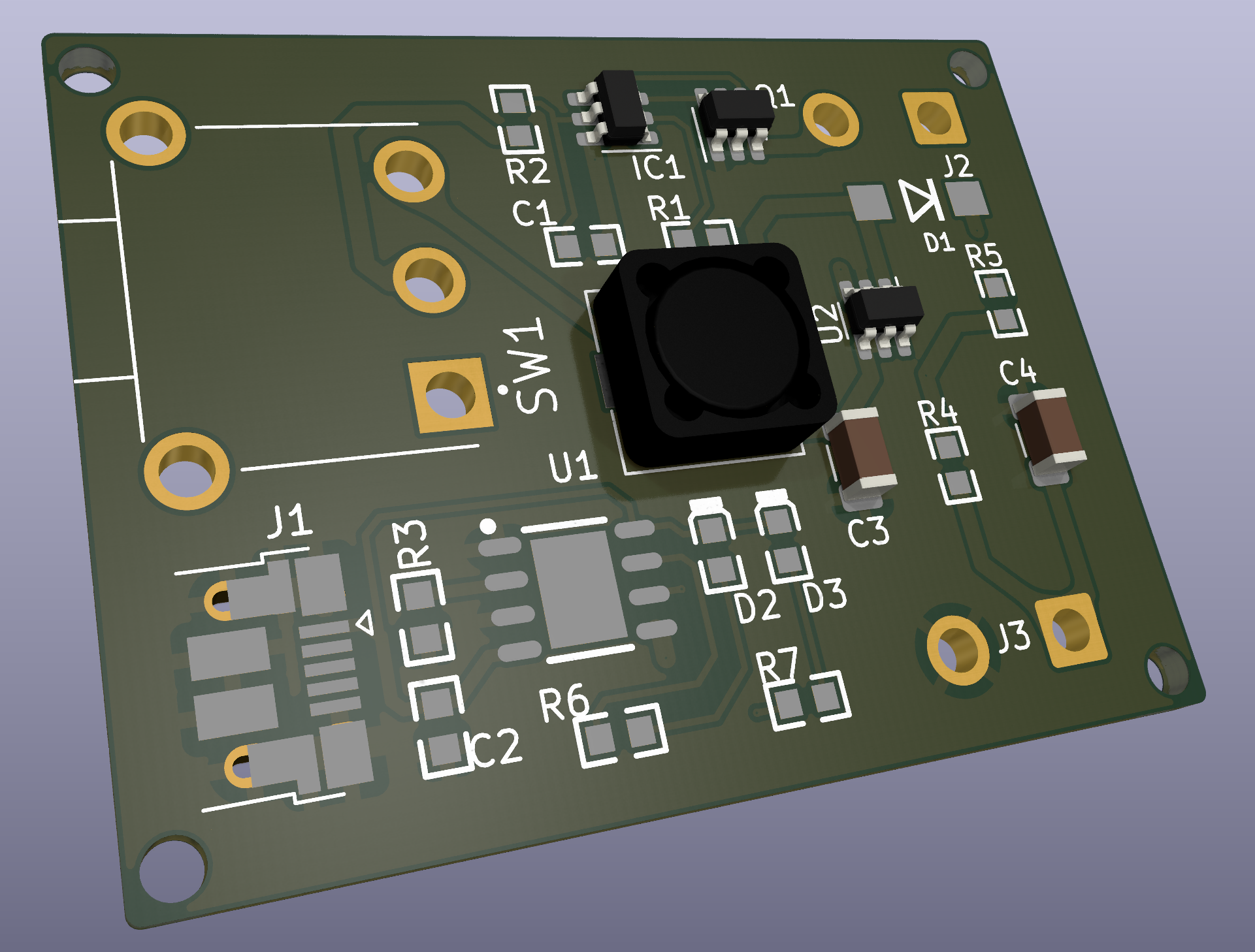
| PCB Preview of the Power | 3D Preview of the PCB |
Three different track widths are used in the PCB design. They are 0.250mm, 0.500mm, and 0.750mm. The track of 0.250mm is used to transfer the signals around the chips. The track of 0.500 mm is used to connect pins involved with the output of the battery. The track of 0.750mm is used to be paths involved with boosted output. Additionally, two copper pour planes of GND are on the front and the back.
| Number | References | Value | Footprint | Quantity | Price |
|---|---|---|---|---|---|
| 1 | C3, C4 | 22uF | C_1206_3216Metric | 2 | US$1.06 |
| 2 | C1 | 0.1u | 0603_R | 1 | US$ 0.0026 |
| 3 | C2 | 10u | 0603_R | 1 | US$ 0.0063 |
| 4 | R5, R6, R7 | 1k | 0603_R | 3 | US$ 0.0033 |
| 5 | R1, R3 | 2k | 0603_R | 2 | US$ 0.0018 |
| 6 | R2 | 100 | 0603_R | 1 | US$ 0.0012 |
| 7 | R4 | 7.5k | 0603_R | 1 | US$ 0.0013 |
| 8 | L1 | 22uH | 75_75_4 | 1 | US$ 0.1676 |
| 9 | D1 | SS34_mdd | SS34 | 1 | US$ 0.0342 |
| 10 | D2 | LED_R | 0603_LED_S1 | 1 | US$ 0.0381 |
| 11 | D3 | LED_G | 0603_LED_S1 | 1 | US$ 0.0381 |
| 12 | U1 | TP4056_[C16581] | SOP-8_EP_150MIL | 1 | US$ 0.2303 |
| 13 | U2 | MT3608 | SOT-23-6 | 1 | US$ 0.1627 |
| 14 | SW1 | SW_DIP_x01 | SW_500SSP3S1M6QEA | 1 | US$3.89 |
| 15 | IC1 | FS312F-G | SOT-23-6 | 1 | US$ 0.16 |
| 16 | Q1 | FS8205 | SOT-23-6 | 1 | US$ 0.1763 |
| 17 | J2, J3 | Conn_01x02_Female | SolderWire-1sqmm_1x02_P5.4mm_D1.4mm_OD2.7mm | 2 | free |
| 18 | J1 | USB_B_Micro | USB_Micro-B_Amphenol_10103594-0001LF_Horizontal | 1 | free |
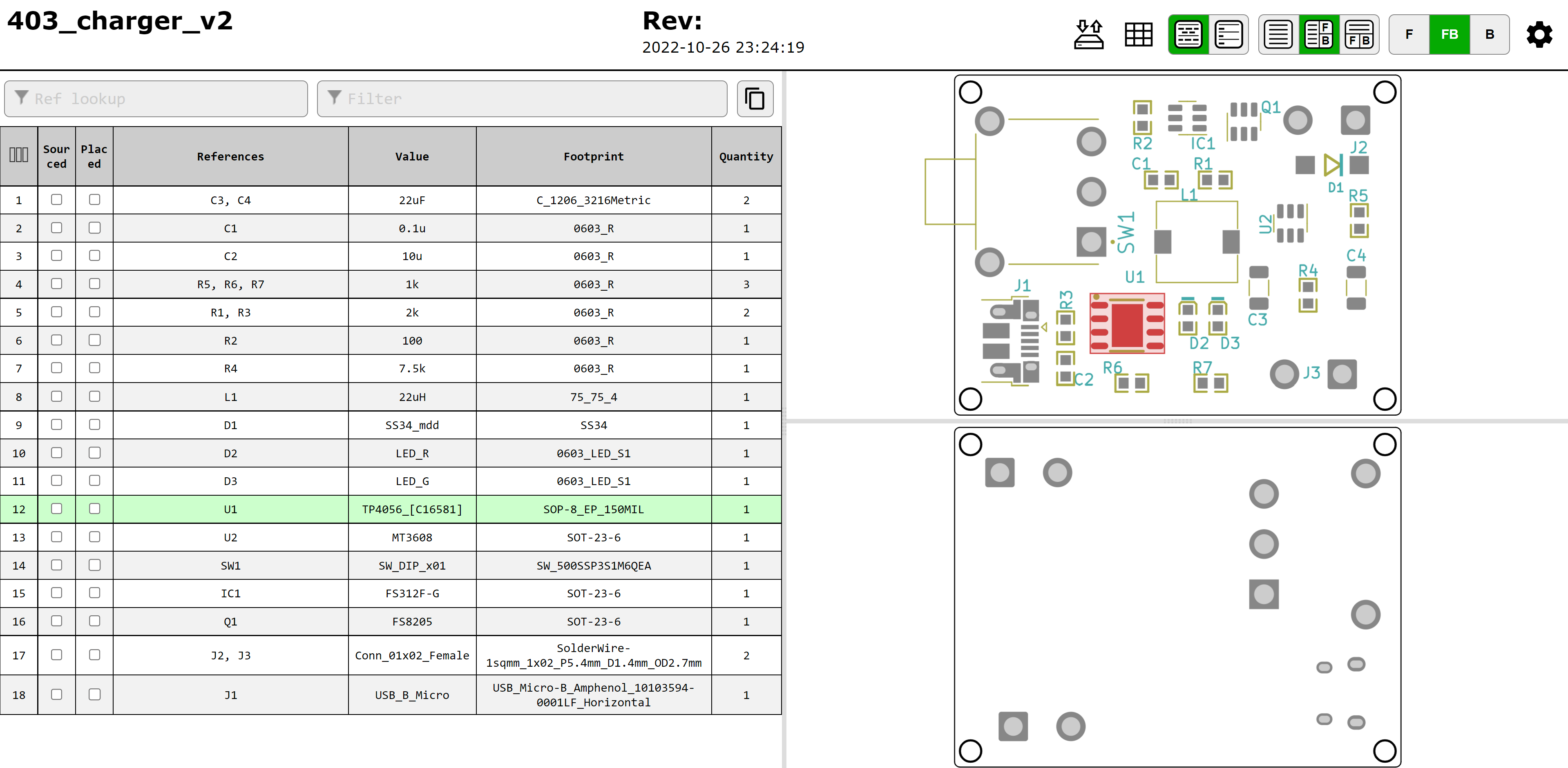
There is also another interactive BOM in the files. The path is "403_charger_v2\bom\ibom.html". In the "ibom.html," you can click the component on the PCB then the corresponding information of the component will be highlighted at the side. The following figure is the preview of the interactive BOM.
 |
|---|
| Preview of the Interactive BOM |
| Qty | Value | Footprint | References |
|---|---|---|---|
| 3 | 1k | lc_lib:0603_R | R5, R6, R7 |
| 2 | 22uF | Capacitor_SMD:C_1206_3216Metric | C3, C4 |
| 2 | 2k | lc_lib:0603_R | R1, R3 |
| 2 | Conn_01x02_Female | Connector_Wire:SolderWire-1sqmm_1x02_P5.4mm_D1.4mm_OD2.7mm | J2, J3 |
| 1 | 0.1u | lc_lib:0603_R | C1 |
| 1 | 100 | lc_lib:0603_R | R2 |
| 1 | 10u | lc_lib:0603_R | C2 |
| 1 | 22uH | 403_charger_new:75_75_4 | L1 |
| 1 | 7.5k | lc_lib:0603_R | R4 |
| 1 | FS312F-G | Package_TO_SOT_SMD:SOT-23-6 | IC1 |
| 1 | FS8205 | Package_TO_SOT_SMD:SOT-23-6 | Q1 |
| 1 | LED_G | lc_lib:0603_LED_S1 | D3 |
| 1 | LED_R | lc_lib:0603_LED_S1 | D2 |
| 1 | MT3608 | Package_TO_SOT_SMD:SOT-23-6 | U2 |
| 1 | SS34_mdd | 403_charger_new:SS34 | D1 |
| 1 | SW_DIP_x01 | 403_charger_new:SW_500SSP3S1M6QEA | SW1 |
| 1 | TP4056_[C16581] | lc_lib:SOP-8_EP_150MIL | U1 |
| 1 | USB_B_Micro | Connector_USB:USB_Micro-B_Amphenol_10103594-0001LF_Horizontal | J1 |
It measures 41.8 × 31.8 mm and has 2 copper layers, 1.6 mm thick.
23 parts, built around the MT3608, FS312F-G and FS8205. The full list of its parts is on this page, with links to each part's symbol and footprint where PCBKit's library has them.
From the EE403-CapStone/Power repository on GitHub, at the commit this page was made from: the board is 403_charger_v2/403_charger_v2.kicad_pcb and its schematic 403_charger_v1/LiPo_Charger_1.kicad_sch. PCBKit opens the board in the browser, with nothing to install.
Its repository states no licence, so its author keeps all rights: ask EE403-CapStone before reusing the design.
cester-ino/OTTO-hardware
those specs refer to the tactile buttons version, but a led backlight button version is in the works too.

alxhoff/gameboy-dmg-pcb
PCB for Gameboy DMG with audio and GPIO expander to provide I2C interface to push buttons

aziraphale/pride-badge-v1
🌈⚡Pride badge PCB with LEDs, STM32, and 3D printed diffuser+case!


sercami97/EstacionMeteorologica
Open source proyect for low cost weather station

