2 layers159 × 140.1 mm
Phazor
skrmsh/skirmish-hardware
Skirmish Hardware © 2022-2023 by Ole Lange is licensed under CC BY-NC-SA 4.0. To view a copy of this license, visit http://creativecommons.org/licenses/by-nc-sa/4.0/
123 parts10

 eduxstad/Emrick
AAMB wearable light strip redesign
Emrick is an open-source printed circuit board by eduxstad, from the eduxstad/Emrick repository on GitHub. It is a 4-layer board of 44.4 × 59.3 mm with 90 parts on 102 nets, routed with 918 tracks and 158 vias.
It is built around the 74HCT541D, CC1312R1F3RGZ and CP2102N-EK, with the TPS61230ARNSR, BLM18HE152SN1 and SP0503BAHTG among its other parts. Its parts include 35 capacitors, 25 resistors, 8 inductors, 6 ICs and 4 connectors.


This folder contains the KiCAD project of the wearable light strip PCB. In the production folder are the gerber and placement files for the latest revision, generated from KiCAD.
This process is meant for creating production files that will be used with JLCPCB. For a different manufacturer the process may be slightly different.
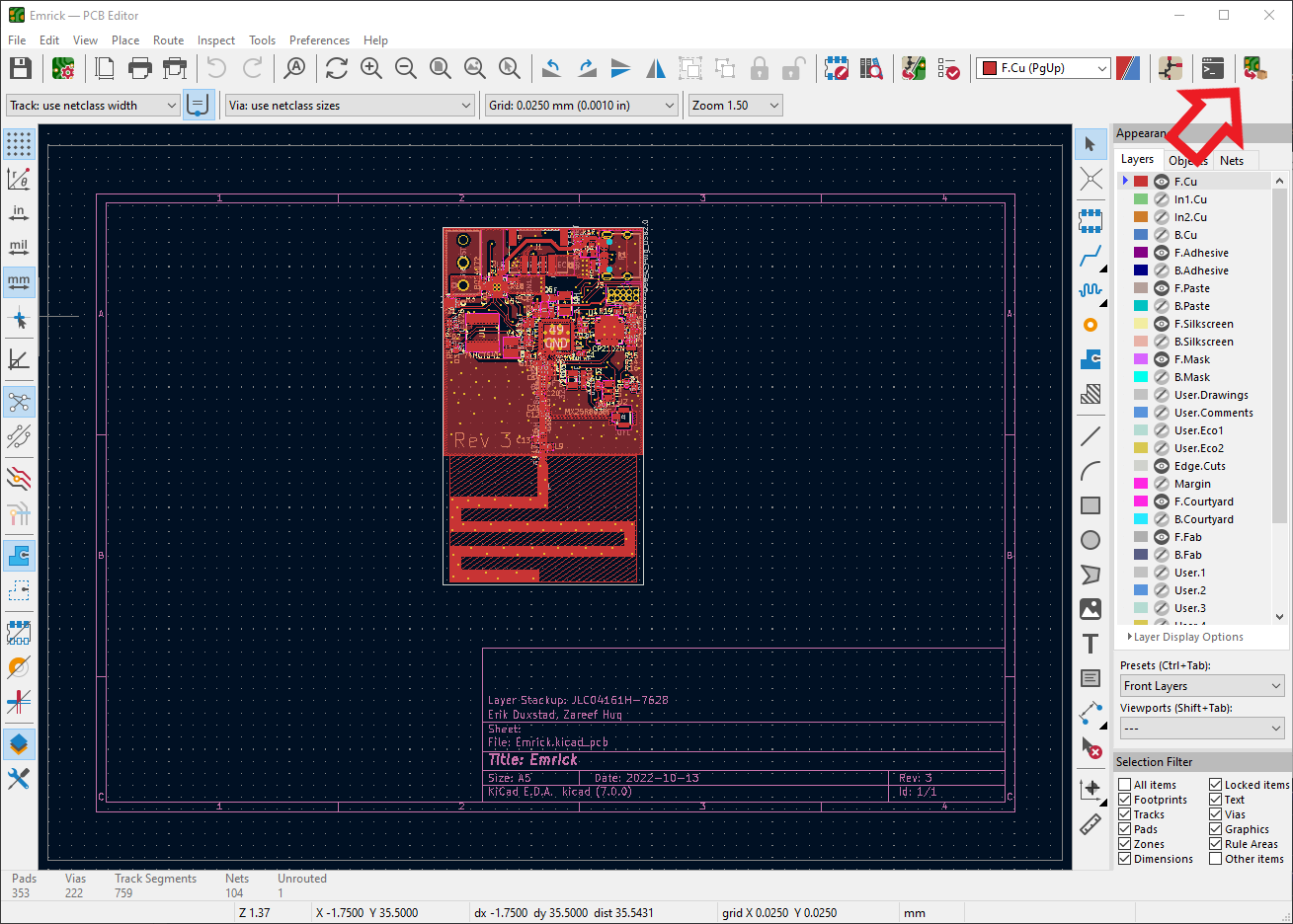 Note that this will also create a bill of materials (BOM) for the PCB. However, the JLCPCB part numbers are not currently added to schematic (there are instructions here) so the latest BOM is kept in
bom.xls.bom.xsl with any new components and their JLCPCB part numbers.Well, you're worried you toasted a board. Here are the steps to make sure that the board is happy. Note that for software/peripherals there is a Smoketest program in the software/cc1310 folder that will test the functionality of all of the peripherals.
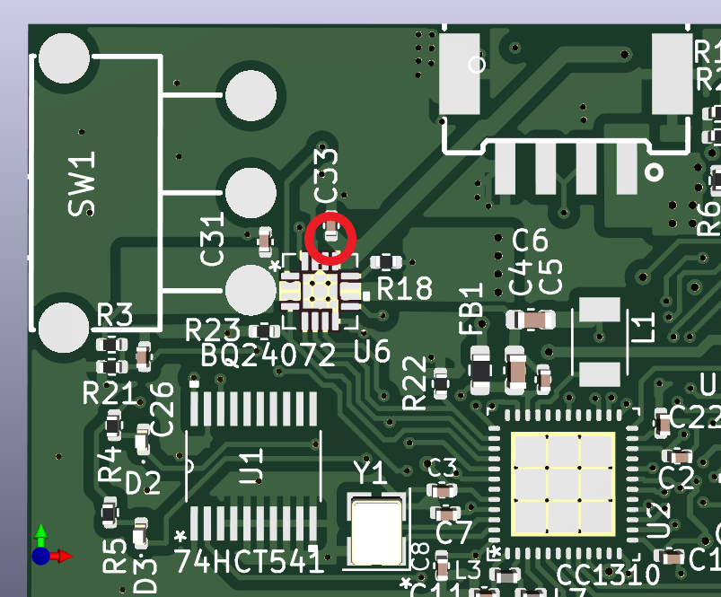
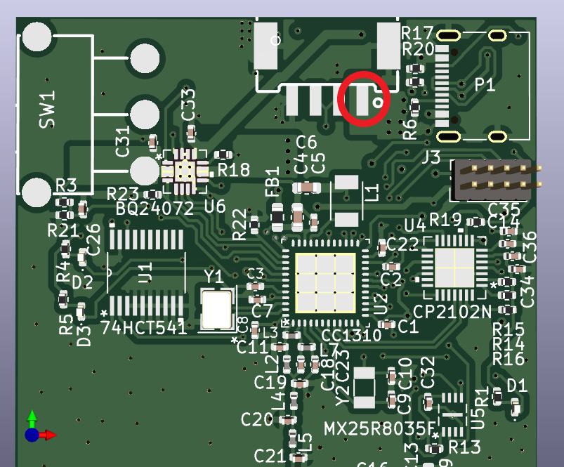
If connected to USB, verify that you are receiving 5V from the VBUS connection. You can use the USB port shielding as ground, and touch the other end of the multimeter to pin 1 of C33. This can vary a few tenths of a volt due to what device you are connected to and how much current you are drawing.
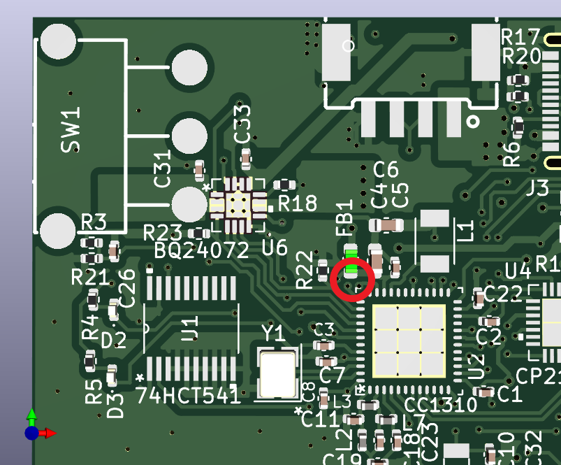
Verify the supply voltages of the CC1310 microcontroller. This is taken from section 12 of the Hardware and PCB Design considerations here.
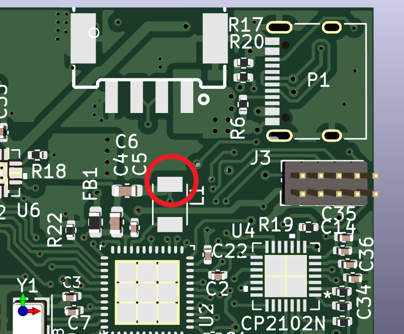
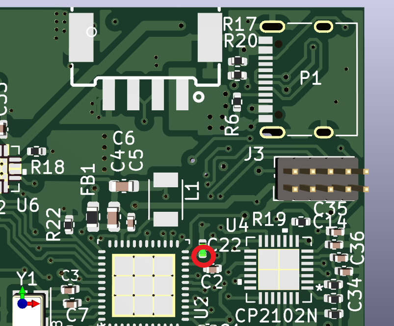 If these voltages check out, it's pretty likely that the CC1310 should be working correctly.
Now we can move on to the boosted 5V LED output.
| Qty | Value | Footprint | References |
|---|---|---|---|
| 11 | 0.1uF | Capacitor_SMD:C_0402_1005Metric | C1, C2, C3, C5, C7, C8, C15, C26, C32, C35, C36 |
| 7 | 10k | Resistor_SMD:R_0402_1005Metric | R11, R14, R15, R16, R22, R23, R24 |
| 4 | 22uF | Capacitor_SMD:C_0603_1608Metric | C4, C6, C29, C30 |
| 3 | 309k | Resistor_SMD:R_0402_1005Metric | R3, R10, R21 |
| 3 | 4.7uF | Capacitor_SMD:C_0402_1005Metric | C14, C31, C34 |
| 3 | Q_NMOS_GSD | Package_TO_SOT_SMD:SOT-23_Handsoldering | Q1, Q2, Q3 |
| 2 | 1.5k | Resistor_SMD:R_0402_1005Metric | R4, R5 |
| 2 | 100k | Resistor_SMD:R_0402_1005Metric | R2, R12 |
| 2 | 100pF | Capacitor_SMD:C_0402_1005Metric | C16, C23 |
| 2 | 3.6pF | Capacitor_SMD:C_0402_1005Metric | C11, C18 |
| 2 | 5.1k | Resistor_SMD:R_0402_1005Metric | R6, R25 |
| 2 | 6.8nH | Inductor_SMD:L_0402_1005Metric | L4, L5 |
| 2 | 7.5nH | Inductor_SMD:L_0402_1005Metric | L2, L7 |
| 2 | ? | Capacitor_SMD:C_0603_1608Metric | C13, L9 |
| 2 | LED | LED_SMD:LED_0402_1005Metric | D2, D3 |
| 1 | 1 uF | Capacitor_SMD:C_0402_1005Metric | C33 |
| 1 | 1.0K | Resistor_SMD:R_0402_1005Metric | R1 |
| 1 | 1.13k | Resistor_SMD:R_0603_1608Metric | R7 |
| 1 | 1.18k | Resistor_SMD:R_0402_1005Metric | R18 |
| 1 | 1.5uH | Inductor_SMD:L_Chilisin_BMRB00060612 | L8 |
| 1 | 10nF | Capacitor_SMD:C_0402_1005Metric | C27 |
| 1 | 10pF | Capacitor_SMD:C_0402_1005Metric | C28 |
| 1 | 10uF | Capacitor_SMD:C_0603_1608Metric | C25 |
| 1 | 12pF | Capacitor_SMD:C_0402_1005Metric | C9 |
| 1 | 15pF | Capacitor_SMD:C_0402_1005Metric | C10 |
| 1 | 1k | Resistor_SMD:R_0402_1005Metric | R19 |
| 1 | 1uF | Capacitor_SMD:C_0402_1005Metric | C22 |
| 1 | 2.21k | Resistor_SMD:R_0603_1608Metric | R8 |
| 1 | 2.2k | Resistor_SMD:R_0402_1005Metric | R13 |
| 1 | 2.7pF | Capacitor_SMD:C_0402_1005Metric | C19 |
| 1 | 22.1k | Resistor_SMD:R_0402_1005Metric | R17 |
| 1 | 27nH | Inductor_SMD:L_0402_1005Metric | L3 |
| 1 | 3.3nH | Inductor_SMD:L_0402_1005Metric | L6 |
| 1 | 32.768kHz | Crystal:Crystal_SMD_3215-2Pin_3.2x1.5mm | Y2 |
| 1 | 3pF | Capacitor_SMD:C_0402_1005Metric | C21 |
| 1 | 47.5k | Resistor_SMD:R_0402_1005Metric | R20 |
| 1 | 48MHz | Crystal:Crystal_SMD_3225-4Pin_3.2x2.5mm | Y1 |
| 1 | 5.1pF | Capacitor_SMD:C_0402_1005Metric | C17 |
| 1 | 6.2pF | Capacitor_SMD:C_0402_1005Metric | C20 |
| 1 | 6.8uH | Inductor_SMD:L_TDK_NLV32_3.2x2.5mm | L1 |
| 1 | 74HCT541 | 74hct541:SN74HCT541PW | U1 |
| 1 | 8.87k | Resistor_SMD:R_0603_1608Metric | R9 |
| 1 | Antenna | RF_Antenna:Texas_SWRA416_868MHz_915MHz | AE1 |
| 1 | BATT_CONN | hirosedf65:DF65-3P-1.7V21 | J4 |
| 1 | BLM18HE152SN1 | Resistor_SMD:R_0603_1608Metric | FB1 |
| 1 | BQ24072 | bq24072:BQ24072TRGTR | U6 |
| 1 | CC1312R1F3RGZ | Package_DFN_QFN:VQFN-48-1EP_7x7mm_P0.5mm_EP5.15x5.15mm | U2 |
| 1 | CP2102N | cp2102n:CP2102N-A02-GQFN28 | U4 |
| 1 | Conn_02x05_Odd_Even | Connector_PinHeader_1.27mm:PinHeader_2x05_P1.27mm_Vertical | J3 |
| 1 | LED_STRIP_CONNECTOR | jstpa:CONN-SMD_SM04B-PASS-TBT-LF-SN | J1 |
| 1 | MX25R8035F | mx25r8:MX25R8035FZUIL0 | U5 |
| 1 | SP0503BAHT | Package_TO_SOT_SMD:SOT-143 | D4 |
| 1 | SW_Push_LED | footprints.pretty:SW-SMD_CHA_C603B-101ML-1SF | SW2 |
| 1 | SW_SPST | switch_original:SW-TH_SS-12F45-GXXX | SW1 |
| 1 | TPS61230ARNSR | tps61230:VQFN7_2X2_TEX | U3 |
| 1 | USB_C_Plug_USB2.0 | Connector_USB:USB_C_Receptacle_XKB_U262-16XN-4BVC11 | P1 |
It measures 44.4 × 59.3 mm and has 4 copper layers, 4.69 mm thick.
90 parts, built around the 74HCT541D, CC1312R1F3RGZ, CP2102N-EK and TPS61230ARNSR. The full list of its parts is on this page, with links to each part's symbol and footprint where PCBKit's library has them.
From the eduxstad/Emrick repository on GitHub, at the commit this page was made from: the board is hardware/Emrick/Emrick.kicad_pcb and its schematic hardware/Emrick/Emrick.kicad_sch. PCBKit opens the board in the browser, with nothing to install.
Its repository states no licence, so its author keeps all rights: ask eduxstad before reusing the design.
skrmsh/skirmish-hardware
Skirmish Hardware © 2022-2023 by Ole Lange is licensed under CC BY-NC-SA 4.0. To view a copy of this license, visit http://creativecommons.org/licenses/by-nc-sa/4.0/


Alexgichamba/lipo-based-power-supply
Battery charger and battery protection PCB with 5V and 3V3 output rails for 1S LiPo battery

May-engineer/EEE3088F-Micromouse-power-module-
repo used to keep track of latest PCB design


anobli/pandora-hw
Open hardware designs for user-controlled smart home devices. Zephyr RTOS + Thread/WiFi connectivity. No cloud dependency, no vendor lock-in.

mik4el/cc1352-swim-thermo
Software and hardware for dual band radio high accuracy swim thermometer