
2 layers80 × 50 mm
OPN
46nori/FMSynthEnsemble
USB MIDI FM synthesizer that supports voice synthesis using CSM (Composite Sinusoidal Model
19 partsMIT

 EduSpectro/EduSpectro4X
ファームウェア・電子回路
EduSpectro4X 07 is an open-source printed circuit board by EduSpectro, from the EduSpectro/EduSpectro4X repository on GitHub, published under the MIT licence. It is a 2-layer board of 57 × 47 mm with 17 parts on 33 nets, routed with 74 tracks and 0 vias.
It is built around the NJM2732D. Its parts include 4 connectors, 3 capacitors, 2 resistors, 2 ICs and 1 switch. It belongs with the RP2350 boards of this library.
ファームウェア・電子回路 📖 総合ガイド(Webサイト)はこちら
概要: 「RP2350とC12880MAを組み合わせた分光器の心臓部です」
分光性能諸元:
特徴: PIOによる高速制御、10回累積計測してによるノイズ軽減、Catmull-Rom補間など。
必要な環境:
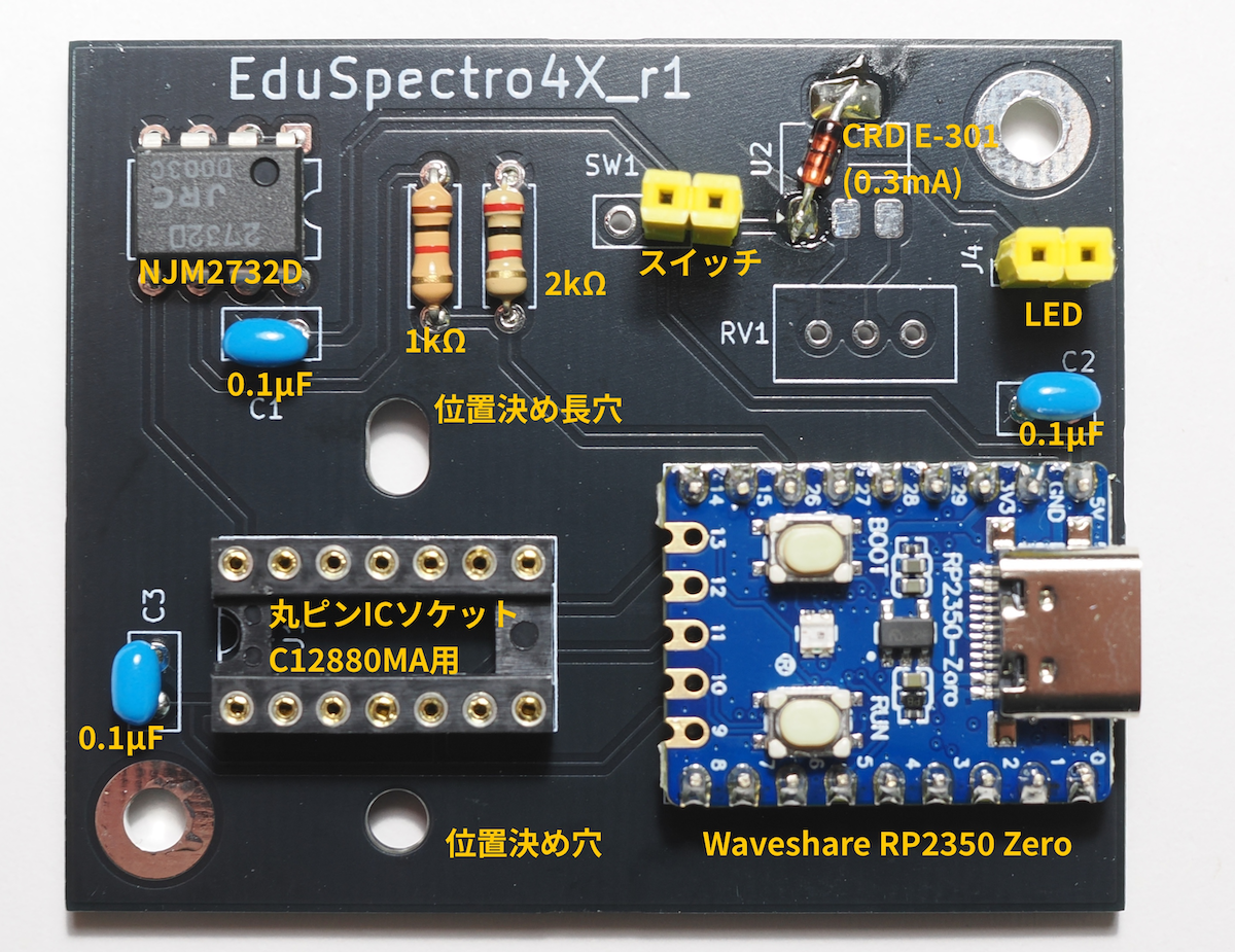
ハードウェアについて:
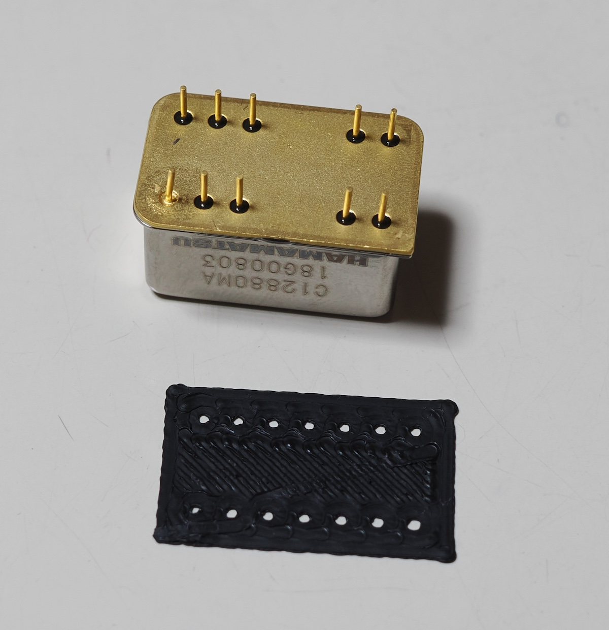
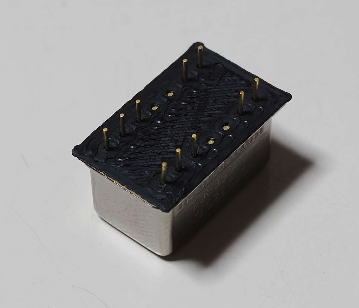
分光センサー底面と丸ピンICソケットの接触について:
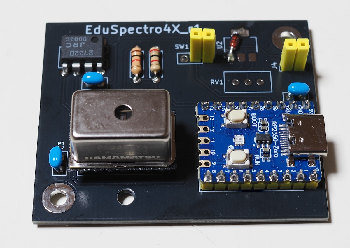
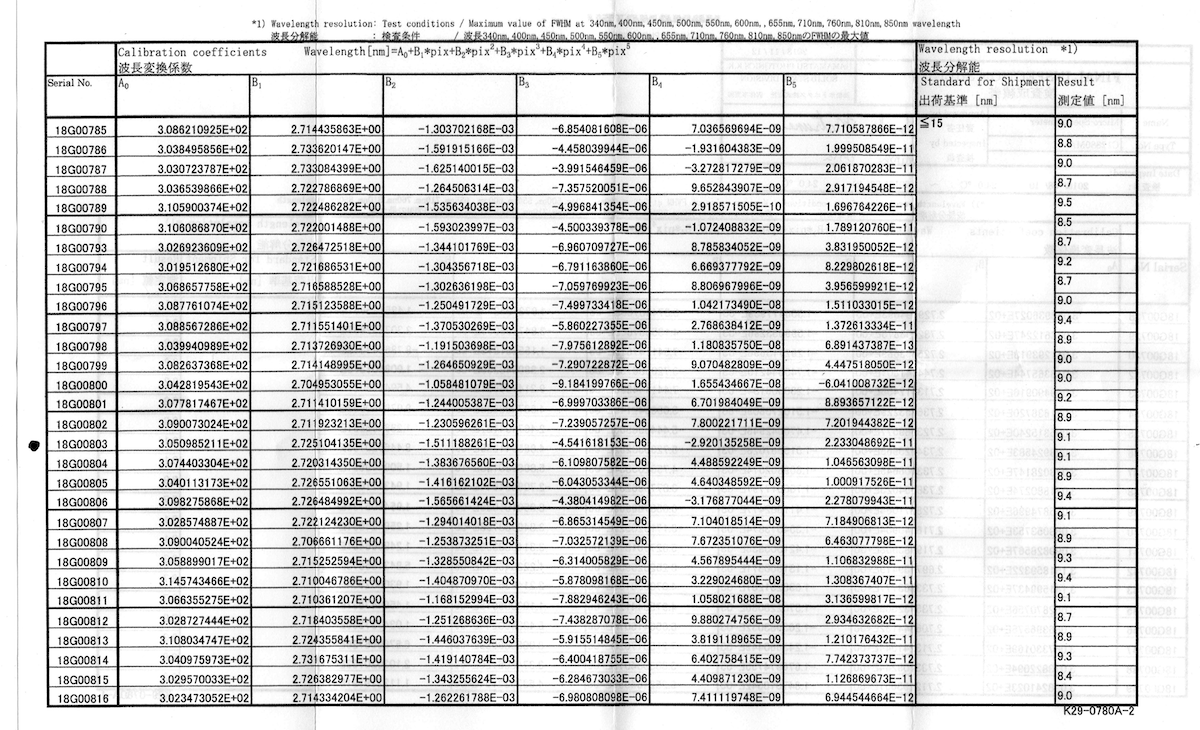
分光センサーのシリアル番号と波長校正データについて:
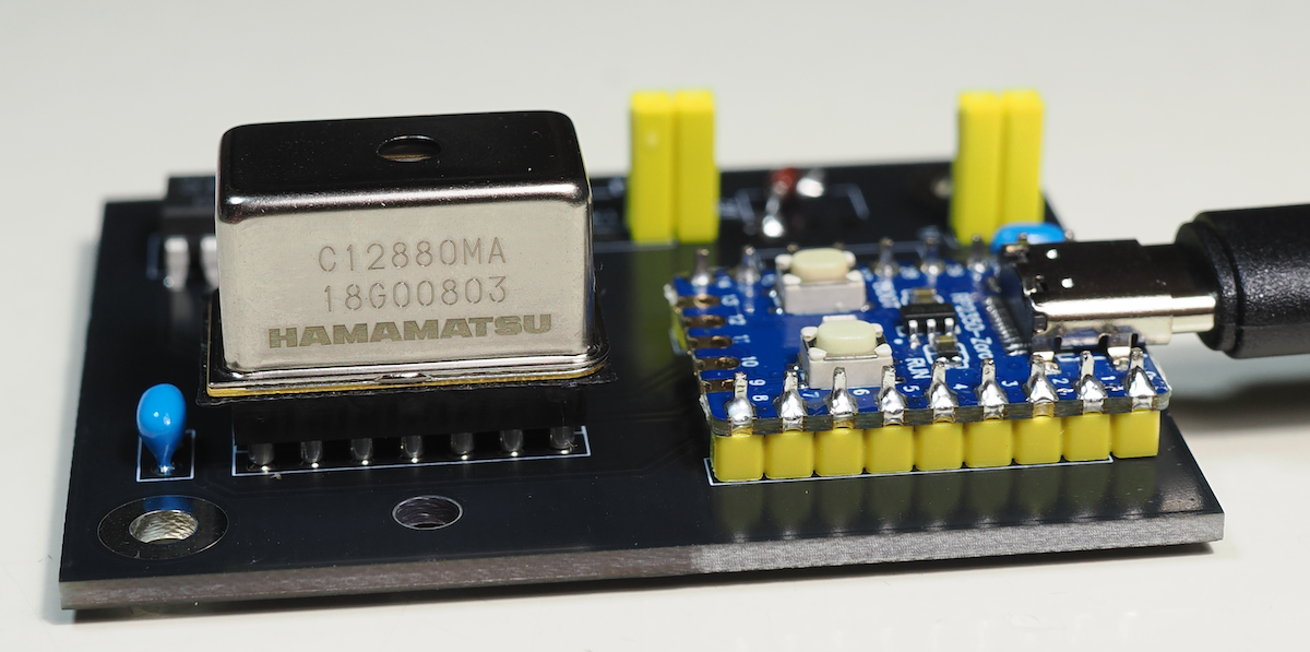
| Qty | Value | Footprint | References |
|---|---|---|---|
| 3 | 0.1u | Capacitor_THT:C_Disc_D5.0mm_W2.5mm_P2.50mm | C1, C2, C3 |
| 2 | RP2350-Zero | Connector_PinHeader_2.54mm:PinHeader_1x09_P2.54mm_Vertical | J2, J3 |
| 1 | 1k | Resistor_THT:R_Axial_DIN0207_L6.3mm_D2.5mm_P7.62mm_Horizontal | R1 |
| 1 | 2k | Resistor_THT:R_Axial_DIN0207_L6.3mm_D2.5mm_P7.62mm_Horizontal | R2 |
| 1 | 500 | Potentiometer_THT:Potentiometer_Bourns_3296W_Vertical | RV1 |
| 1 | Conn_01x02_Pin | Connector_PinHeader_2.54mm:PinHeader_1x02_P2.54mm_Vertical | J4 |
| 1 | Conn_02x07_Counter_Clockwise | Package_DIP:DIP-14_W7.62mm_Socket | J1 |
| 1 | NJM2732 | Package_DIP:DIP-8_W7.62mm | U1 |
| 1 | NSI45020JZ-D | Package_TO_SOT_SMD:SOT-223-3_TabPin2 | U2 |
| 1 | SW_SPDT | Connector_PinHeader_2.54mm:PinHeader_1x03_P2.54mm_Vertical | SW1 |
The 13 most common of 17 parts.
It measures 57 × 47 mm and has 2 copper layers, 1.6 mm thick.
17 parts, built around the NJM2732D. The full list of its parts is on this page, with links to each part's symbol and footprint where PCBKit's library has them.
From the EduSpectro/EduSpectro4X repository on GitHub, at the commit this page was made from: the board is hardware/EduSpectro4X_07/EduSpectro4X_07.kicad_pcb and its schematic hardware/EduSpectro4X_07/EduSpectro4X_07.kicad_sch. PCBKit opens the board in the browser, with nothing to install.
Its repository publishes it under the MIT licence: you may reuse it on that licence's terms (keep the author's notice, and for a copyleft licence share your changes alike).
46nori/FMSynthEnsemble
USB MIDI FM synthesizer that supports voice synthesis using CSM (Composite Sinusoidal Model


hoglet67/RGBtoHDMI
Bare-metal Raspberry Pi project that provides pixel-perfect sampling of Retro Computer RGB/YUV video and conversion to HDMI


hackclub/OnBoard
💡 Join 1,000 teenagers and make your first PCB with a $100 grant!

DDeGonge/OS-ARM
This arm is not industrial and it will not be fast, but that is not my goal. But it will hopefully be a very nice looking arm fully capable of 6dof motion, cheap enough to keep it accessable but capable enough to…
