Skip to the content
2 layers79.3 × 46.4 mmRook, the printed circuit board in 3D

Rook is an open hardware radio board from Edge Collective. It is built for nodes that sit outdoors on a battery and keep working: mesh repeaters, remote sensors, and anything else that needs to send data a long way…

Size
79.3 × 46.4 mm
Copper layers
2
Thickness
1.6 mm
Parts
51
Nets
32
Pads
179
Tracks, vias
671, 184
Pours
2
Routed
Yes
KiCad
KiCad 8.0 (file 20240108)
Created
21 Sep 2026
Updated
21 Sep 2026

Overview

Rook is an open-source printed circuit board by edgecollective, from the edgecollective/rook repository on GitHub. It is a 2-layer board of 79.3 × 46.4 mm with 51 parts on 32 nets, routed with 671 tracks and 184 vias.

It is built around the WIO-SX1262. Its parts include 24 resistors, 11 connectors, 4 ICs and 1 transistor. It belongs with the radio and wireless boards and the nRF52 and nRF5x boards of this library.

Main components

1

README

README.md

Rook

A small, low-power LoRa board for off-grid mesh radio and remote sensing.

Rook is an open hardware radio board from Edge Collective. It is built for nodes that sit outdoors on a battery and keep working: mesh repeaters, remote sensors, and anything else that needs to send data a long way without cell service or WiFi. It runs MeshCore firmware, and it is the board inside the Mesh Radio Water Level Kit.

This repo holds the hardware design files, ready-to-flash firmware, and documentation. The same content is published at edgecollective.io/rook.

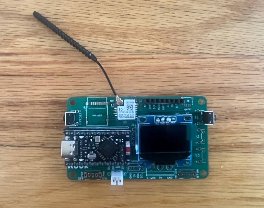
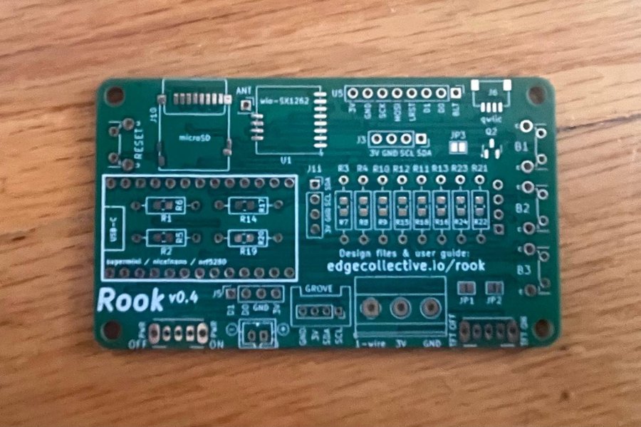
AssembledBare PCB
Rook v4, assembled, with OLED display, radio module and antennaRook v4 bare PCB

Buy one: assembled and flashed ($65), or as a bare PCB ($10), at the Edge Collective shop.


Contents


What's on the board

The current revision is Rook v4. The silkscreen reads v0.4.

Size79 × 46 mm
MicrocontrollernRF52840, on a plug-in Pro Micro–format module (SuperMini / nice!nano compatible), with USB-C and Bluetooth LE
RadioSeeed Wio-SX1262 LoRa module, up to 22 dBm, with a u.FL antenna connector
FrequencyAssembled boards ship set up for 915 MHz (US)
DisplaySSD1306 OLED over I²C
StoragemicroSD card slot
Power2-pin JST battery connector, on/off switch, and battery voltage sensing
ButtonsReset, plus three user-button positions (B1–B3)

Connectors

LabelConnectorPins
J6QwiicI²C
GROVEGroveGND, 3V, SDA, SCL
J34-pin header3V, GND, SCL, SDA
—3-position screw terminal1-wire, 3V, GND
J54-pin headerD1, D0, GND, 3V
U58-pin header for an ST7789 TFT display (SPI), with a backlight on/off jumper3V, GND, SCK, MOSI, LRST, D1, D0, BLT

The MeshCore build for Rook supports AHT20 (AHTx0), BME280 and BMP280 environmental sensors on the I²C bus, and a serial GPS.


Firmware

Pre-built MeshCore firmware for Rook. Download the .uf2 file that fits how you want to use the board:

FirmwareUse it forDownload
RepeaterA standalone node that relays mesh traffic and extends your network's range. Leave it somewhere high, on a battery or solar.Rook_repeater_apr14_2026.uf2 · MeshCore v1.13.0
Companion radio (Bluetooth)Pair the board with the MeshCore app on your phone over Bluetooth, and send and receive messages on the mesh.rook_companion_radio_ble_v0.4.uf2 · MeshCore v1.15.0

An older companion build, on MeshCore v1.13.0, is also available: rook_comparion_radio_ble_april_7.uf2.

Assembled boards from the shop come with MeshCore already installed. You only need these files to switch roles or reflash a board.

To build the firmware yourself, the Rook board definition is in variants/rook of edgecollective/MeshCore-rook.


Flashing firmware

Rook uses the standard nRF52840 UF2 bootloader, so you don't need any special tools:

  1. Download the .uf2 file you want from the firmware table.
  2. Plug the board into your computer with a USB-C cable (into the port on the microcontroller module).
  3. Double-tap the RESET button. The board shows up on your computer as a USB drive.
  4. Drag the .uf2 file onto that drive.
  5. The drive disappears when the copy finishes, and the board restarts with the new firmware.

If no drive appears, try a different USB cable, because some cables only carry power. Then double-tap RESET a little faster.


Hardware design files

Rook is designed in KiCad. The files for the current board, v4, are in hardware/v0.4/rook/:

FileWhat it is
rook.pdfSchematic, as a PDF
rook_v0.4_gerbers.zipGerbers and drill file, ready to upload to a PCB fab
rook.kicad_proKiCad project. Open this, and the schematic (rook.kicad_sch) and layout (rook.kicad_pcb) come with it.
footprints/, symbols/Custom footprints and symbols the project uses
plate/A mounting plate for the board (OpenSCAD source and SVG)

Earlier revisions are kept for reference in hardware/v0.1/, v0.2/ and v0.3/.


Building your own

The bare PCB is for people who solder, want to change the design, or need a handful of boards cheaply. You'll need to source the microcontroller module, the Wio-SX1262 radio, the OLED, and the passive parts yourself, then flash the firmware as described above.

Questions, fixes and improvements are welcome. Please open an issue or a pull request.


Made by Edge Collective.

Parts

51
QtyValueFootprintReferences
12RResistor_THT:R_Axial_DIN0207_L6.3mm_D2.5mm_P10.16mm_HorizontalR1, R2, R3, R4, R10, R11, R12, R13, R14, R19, R21, R23
11RResistor_SMD:R_0805_2012Metric_Pad1.20x1.40mm_HandSolderR5, R6, R7, R8, R9, R15, R17, R18, R20, R22, R24
4MountingHoleMountingHole:MountingHole_3.2mm_M3H1, H2, H3, H4
4SW_PushButton_Switch_THT:SW_Tactile_SPST_Angled_PTS645Vx31-2LFSB1, B2, B3, RESET1
3Jumper_2_OpenJumper:SolderJumper-2_P1.3mm_Open_Pad1.0x1.5mmJP1, JP2, JP3
2Conn_01x03_Socketfootprints:SSW_1825232-1J8, TFT_BL1
2Conn_01x04_Pinfootprints:ssd1306_aJ3, J11
110KResistor_SMD:R_0805_2012Metric_Pad1.20x1.40mm_HandSolderR16
12N7002Package_TO_SOT_SMD:SOT-23Q2
1Conn_01x01_SocketConnector_PinSocket_2.54mm:PinSocket_1x01_P2.54mm_VerticalJ4
1Conn_01x02_SocketConnector_JST:JST_PH_B2B-PH-K_1x02_P2.00mm_VerticalJ1
1Conn_01x04_Pinfootprints:gps_ublox_blueJ2
1Conn_01x04_Socketfootprints:JST_SH4_SKINNYJ6
1Conn_01x04_SocketConnector_PinSocket_2.54mm:PinSocket_1x04_P2.54mm_VerticalJ5
1Micro_SD_Cardfootprints:DM3D-SF_outlineJ10
1Screw_Terminal_01x03TerminalBlock_Phoenix:TerminalBlock_Phoenix_MKDS-1,5-3-5.08_1x03_P5.08mm_HorizontalJ7
1grove_afootprints:grove_aU4
1nice_nano_cleanfootprints:nice_nano_cleanestU2
1wio-sx1262wio-sx1262:wio-sx1262-extendedU1
1~footprints:st7789_154in_240x240U5

More from edgecollective/rook

2
  • 2 layers91.2 × 53.1 mmRook, the printed circuit board in 3D

    Rook

    edgecollective/rook

    Rook is an open hardware radio board from Edge Collective. It is built for nodes that sit outdoors on a battery and keep working: mesh repeaters, remote sensors, and anything else that needs to send data a long way…

    41 parts
  • 2 layers79 × 51 mmRook, the printed circuit board in 3D

    Rook

    edgecollective/rook

    Rook is an open hardware radio board from Edge Collective. It is built for nodes that sit outdoors on a battery and keep working: mesh repeaters, remote sensors, and anything else that needs to send data a long way…

    40 parts

Similar boards

  • 2 layers79 × 30 mmLIA, the printed circuit board in 3D

    LIA

    JGAguado/LIA

    Low-power pet tracking platform built around Meshtastic and LoRa mesh networking

    81 parts29
  • 4 layers42.5 × 32 mmMeshlet, the printed circuit board in 3D

    Meshlet

    dj505/Meshlet

    A feature-packed LoRa mesh network node

    101 parts7
  • 2 layers50 × 60 mmGO, the printed circuit board in 3D

    GO

    Ainacteru/GO

    The source code for the GO PCB

    72 parts1
  • 2 layers40 × 50 mmSensor Station, the printed circuit board in 3D

    Sensor Station

    BeeEyeIoT/sensor-station-board

    Complete KiCAD project for a sensor data collection station

    39 parts
  • 6 layers43 × 82.4 mmCmd z5, the printed circuit board in 3D

    Cmd z5

    befinitiv/cmd-z5-pager

    Replacement PCB & Software to turn Sony CMD-Z5 into a Meshtastic/Lorawan pager

    120 parts
  • 2 layers65.5 × 30.3 mmLoraHat, the printed circuit board in 3D

    LoraHat

    joaouzeda/LoRa-Esp32_RaspbeeryPi0W_Hat

    Project Description An Esp32 with LoRa to connect with a Raspberry Pi Zero W using serial Pins.

    9 parts
  • 2 layers17.8 × 21.4 mmSeeed xiao esp32s3-expander, the printed circuit board in 3D

    Seeed xiao esp32s3-expander

    lucg/seeed-xiao-esp32s3-expander

    An expansion board for the Seeed Studio XIAO ESP32-S3 (Plus) using the B2B connector

    15 partsCC-BY-SA-4.0
  • 4 layers85 × 50 mmWeather Kit Project, the printed circuit board in 3D

    Weather Kit Project

    Mikecerc/WeatherKit_MainBoard

    KiCAD Schematic Files for the weatherkit main board

    98 parts

Questions

How big is the Rook PCB?

It measures 79.3 × 46.4 mm and has 2 copper layers, 1.6 mm thick.

What parts does the Rook use?

51 parts, built around the WIO-SX1262. The full list of its parts is on this page, with links to each part's symbol and footprint where PCBKit's library has them.

Where can I download the Rook KiCad files?

From the edgecollective/rook repository on GitHub, at the commit this page was made from: the board is hardware/v0.4/rook/rook.kicad_pcb and its schematic hardware/v0.1/rook/rook.kicad_sch. PCBKit opens the board in the browser, with nothing to install.

Can I use the Rook design in my own project?

Its repository states no licence, so its author keeps all rights: ask edgecollective before reusing the design.