

2 layers41 × 26 mm
AD7705 Basic
ebozulu1metu/SpectrumAnalyzerRaspi
Audio Level Indicator and Spectrum Analyser for the Raspberry Pi (Zero).
11 partsMIT

 ebozulu1metu/SpectrumAnalyzerRaspi
Audio Level Indicator and Spectrum Analyser for the Raspberry Pi (Zero).
Kicad rtep audio spectrum analyser is an open-source printed circuit board by ebozulu1metu, from the ebozulu1metu/SpectrumAnalyzerRaspi repository on GitHub, published under the MIT licence. It is a 2-layer board of 30 × 65 mm with 64 parts on 58 nets, routed with 231 tracks and 10 vias.
It is built around the MMPQ3904 and SPH0645LM4H-B. Its parts include 28 resistors, 8 diodes, 2 capacitors, 2 transistors and 1 connector. It belongs with the audio and music and sensors and measurement boards of this library.
#Real Time Spectrum Analyser
Audio Level Indicator and Spectrum Analyser for the Raspberry Pi (Zero).
The contents of this repository were part of a university project and is no longer being maintained. Further information on the project can be found in the wiki.
Install BCM 2835 Library
tar zxvf bcm2835-1.52.tar.gz
cd bcm2835-1.52
./configure
make
sudo make check
sudo make install$ sudo apt-get install qt4-dev-tools libqt4-dev qt4-qmake g++ make
$ sudo apt-get install libqwt-dev libqwt-doc libqwt6
$ sudo apt-get install xorgThe goal of this project is to provide a hardware and software solution for a real-time audio level indicator and spectrum analyser for the Raspberry Pi Zero.
The Raspberry Pi Zero can be configured as a USB virtual network gadget can can communicate to a PC through an SSH network connection. The user interface is provided making use of X forwarding using the X Windows System with the Pi Zero hosting the application.
The original idea for the project was unfortunately not completed due to hardware development and fabrication delays. The PCB was fabricated in China and the time required for fabrication and delivery meant that there was little time to write and test software for the platform.
The AD7705 ADC was used as a backup to demonstrate real time data acquisition using SPI and to demonstrate the QT spectrum analyser.
To build:
$ git clone git@github.com:RTEP13/rtep-spectrum-analyser.git
$ cd rtep-spectrum-analyser/project/source/software/qt_interface
$ qmake
$ make
To run software from directory qt_interface:
$ ./qtexample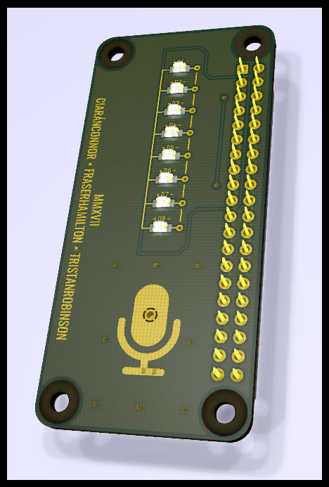
| Qty | Value | Footprint | References |
|---|---|---|---|
| 8 | 10kΩ | PASSIVE:R-0603 | R2, R5, R8, R11, R14, R17, R20, R23 |
| 8 | 120Ω | PASSIVE:R-0603 | R3, R6, R9, R12, R15, R18, R21, R24 |
| 8 | 1kΩ | PASSIVE:R-0603 | R1, R4, R7, R10, R13, R16, R19, R22 |
| 8 | VAL** | STITCH | STITCH, STITCH, STITCH, STITCH, STITCH, STITCH, STITCH, STITCH |
| 8 | VAL** | VIAMASK | VIAMASK, VIAMASK, VIAMASK, VIAMASK, VIAMASK, VIAMASK, VIAMASK, VIAMASK |
| 5 | LG-R971-KN-1 | OSRAM:CHIPLED-0805 | D4, D5, D6, D7, D8 |
| 4 | MOUNTING-HOLE | MOUNTING-HOLE, MOUNTING-HOLE, MOUNTING-HOLE, MOUNTING-HOLE | |
| 3 | 51Ω | PASSIVE:R-0603 | R25, R26, R27 |
| 2 | LY-R976-PS-36 | OSRAM:CHIPLED-0805 | D2, D3 |
| 2 | MMPQ3904 | FAIRCHILD:MMPQ3904 | Q1, Q2 |
| 1 | 0.1µF | PASSIVE:C-0603 | C2 |
| 1 | 100kΩ | PASSIVE:R-0603 | R28 |
| 1 | 200pF | PASSIVE:C-0603 | C1 |
| 1 | LH-R974-LP-1 | OSRAM:CHIPLED-0805 | D1 |
| 1 | LOGO | GRAPHICS:MICROPHONE | G*** |
| 1 | LOGO | GRAPHICS:BY | G*** |
| 1 | RASPBERRY PI GPIO | RASPBERRY-PI:GPIO | P1 |
| 1 | SPH0645LM4H-B | KNOWLES:SPH0645LM4H-B | MK1 |
ebozulu1metu/SpectrumAnalyzerRaspi
Audio Level Indicator and Spectrum Analyser for the Raspberry Pi (Zero).


UBC-Thunderbots/Electrical
All things electrical, from radio communication to BLDC motors. Zappity zap!


Arkos-Engineering/HT-15_hardware
We can split this out into separate repos later, right now its very convenient to have everything here.

emertcakir/OpenAirScope
Open-source air quality and environmental monitoring node with STM32H743 + ESP32-C3, LoRaWAN, RS485, USB-C, Li-ion charging, and multi-sensor support.
It measures 30 × 65 mm and has 2 copper layers, 1.6 mm thick.
64 parts, built around the MMPQ3904 and SPH0645LM4H-B. The full list of its parts is on this page, with links to each part's symbol and footprint where PCBKit's library has them.
From the ebozulu1metu/SpectrumAnalyzerRaspi repository on GitHub, at the commit this page was made from: the board is project/source/hardware/SPH0645LM4H-B_Mic_Board/kicad-rtep-audio-spectrum-analyser.kicad_pcb. PCBKit opens the board in the browser, with nothing to install.
Its repository publishes it under the MIT licence: you may reuse it on that licence's terms (keep the author's notice, and for a copyleft licence share your changes alike).