
2 layers103 × 30.5 mm

This simple board allows you to neatly and painlessly install LEDs on top of a rotary encoder for use with transparent/translucent knobs.
Enc led is an open-source printed circuit board by dwhinham, from the dwhinham/encoder-backlight-pcb repository on GitHub, published under the CC-BY-SA-4.0 licence. It is a 2-layer board of 16 × 20.8 mm with 9 parts on 5 nets, routed with 68 tracks and 0 vias.
Its parts include 4 connectors, 3 diodes and 1 resistor. It belongs with the audio and music boards of this library.

This simple board allows you to neatly and painlessly install LEDs on top of a rotary encoder for use with transparent/translucent knobs.
I designed this board when building a MIDIbox SID synthesizer based on the MB6582 design. The idea was inspired by Hawkeye's control surface build tutorial for the MB6582, but I didn't think I'd personally be able to do a very neat job with enamel wire, and so I decided to design a simple PCB to make it easier to achieve this kind of lighting.
The PCB has been verified to fit perfectly over Alpha Taiwan RE160F-40E3-20A-24P-003 and Bourns PEC16-4220F-N0024.


The PCB has space for three surface-mount LEDs and one resistor. The size of all parts is 0603 imperial (1608 metric).
There are multiple + (positive) terminals that you can use to daisy-chain multiple PCBs together if you need to.
The three LEDs are wired in series, and share a common resistor (R1). The proper value for R1 will vary depending on the specifications of your LED and the voltage of your power source.
If your LEDs have a low enough voltage drop, you may be able to just bridge R1 (or use a 0 ohm resistor) and use a 5V power source. The amber LEDs I used did not light up at all this way however, and so I chose to use a 9V source instead.
You can use a simple LED calculator to help choose the right value for R1. In my case, using the datasheet for my amber LEDs I entered the following information into the calculator:
The result was 150 ohms, and so that's the value I used for R1.

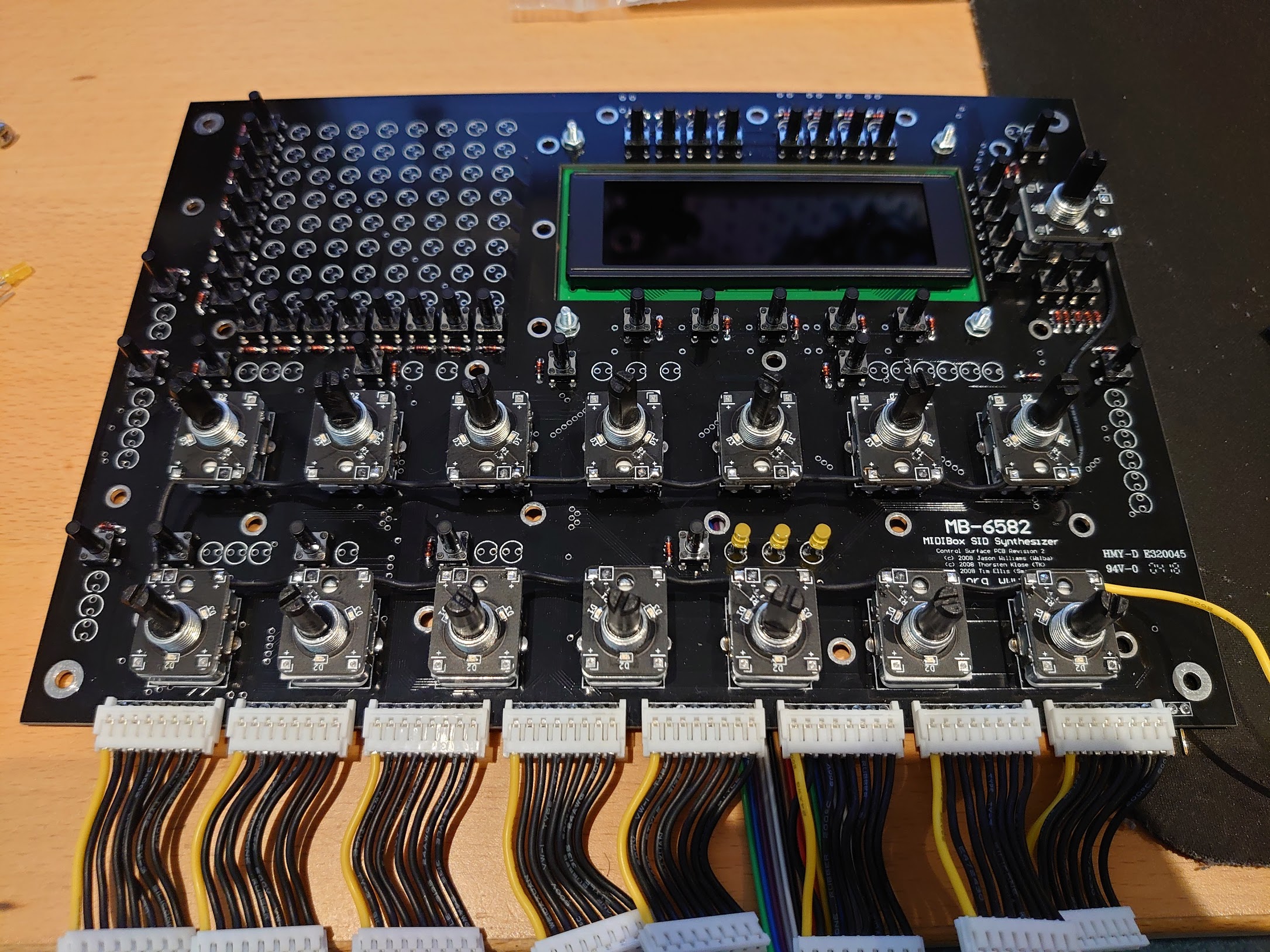
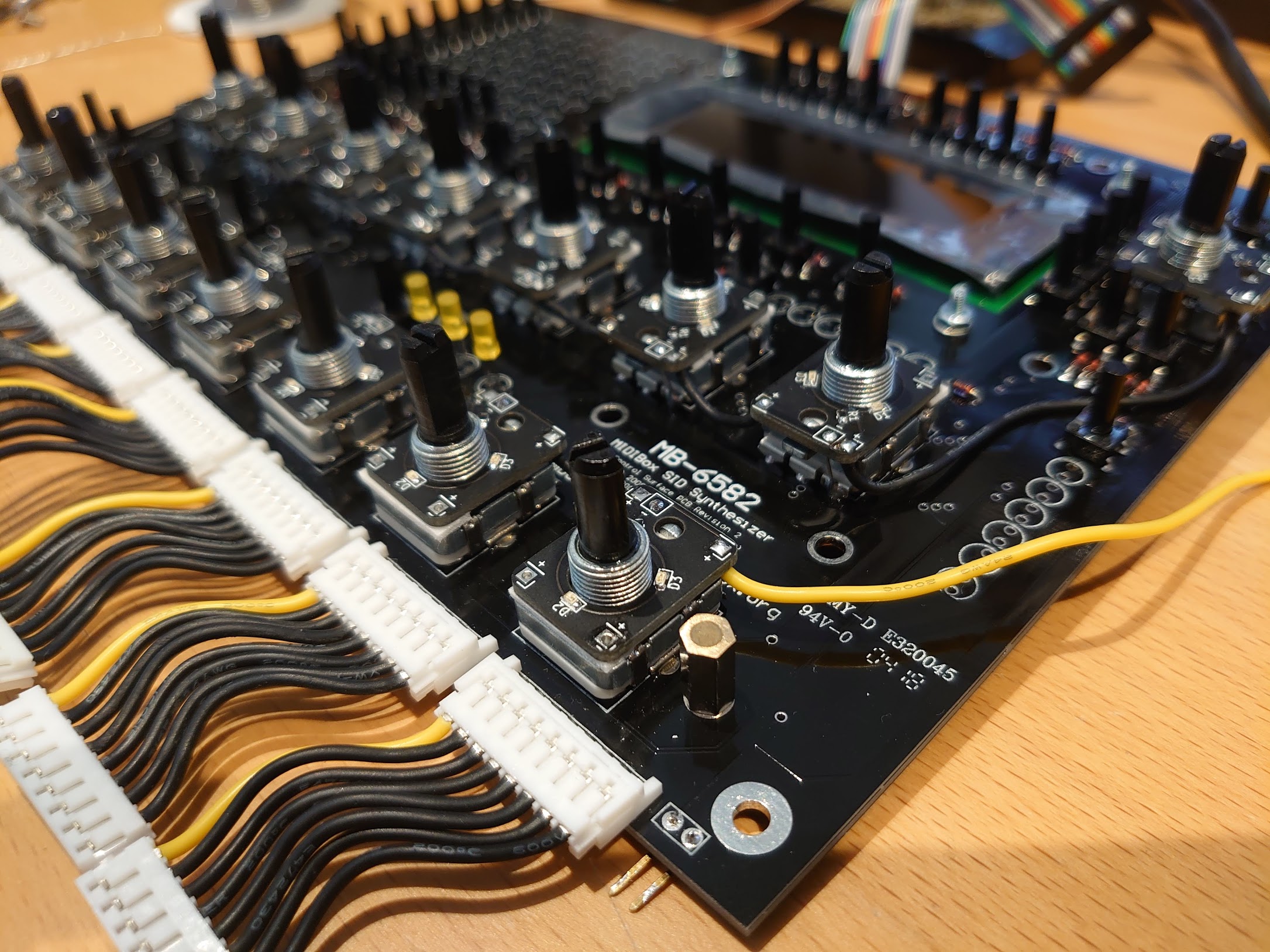
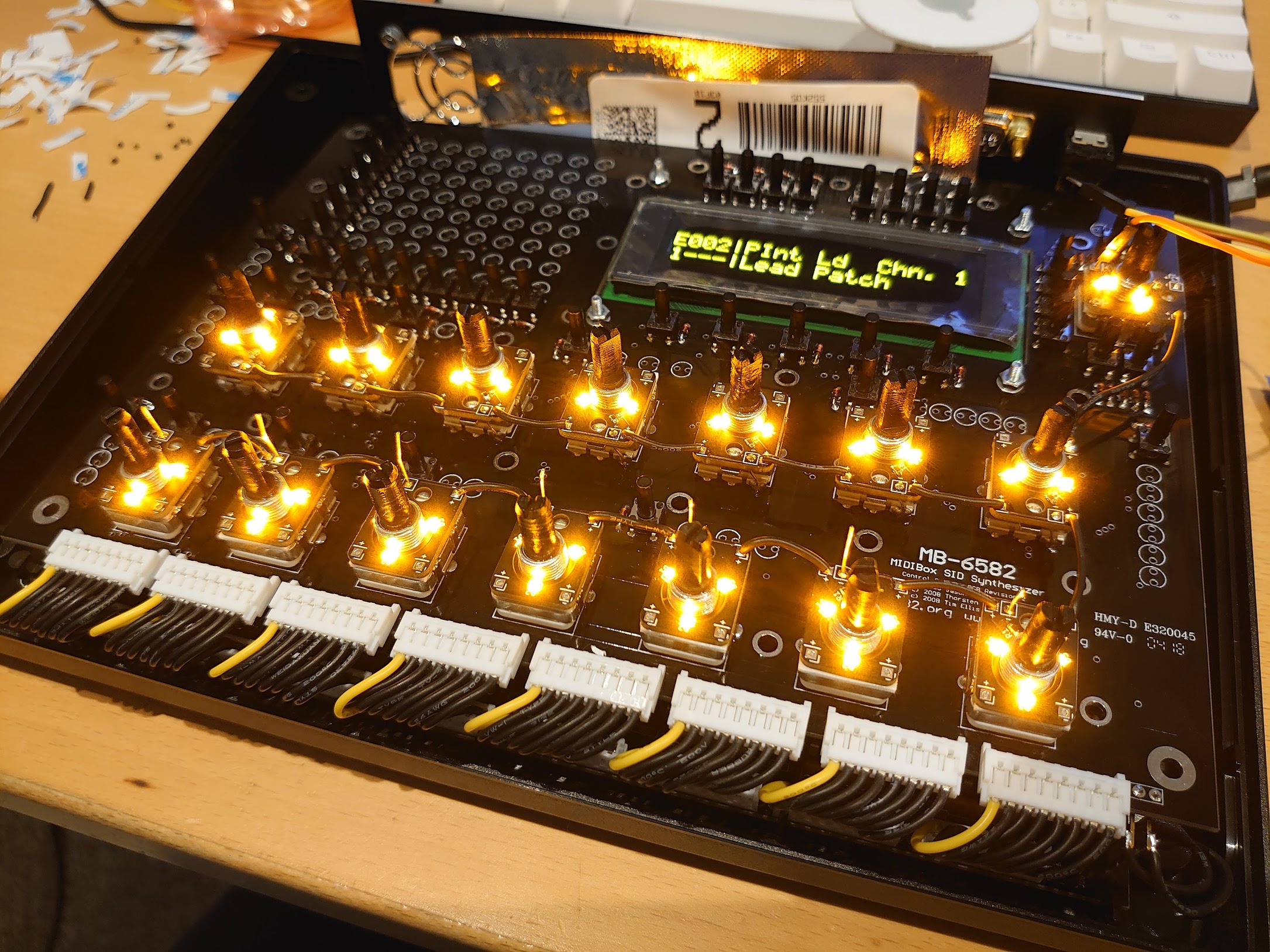
Note: In the last photo above, the wires are shown above the PCBs. This was a mistake, as when test-fitting the metal front panel, there wasn't quite enough clearance, and so I moved them below the PCBs instead. I recommend you do the same.
| Qty | Value | Footprint | References |
|---|---|---|---|
| 3 | Conn_01x01_Female | Connector_PinHeader_2.54mm:PinHeader_1x01_P2.54mm_Vertical | J2, J3, J4 |
| 3 | LED | LED_SMD:LED_0603_1608Metric | D1, D2, D3 |
| 1 | Conn_01x02_Female | Connector_PinHeader_2.54mm:PinHeader_1x02_P2.54mm_Vertical | J1 |
| 1 | R | Resistor_SMD:R_0603_1608Metric | R1 |
The 8 most common of 9 parts.
It measures 16 × 20.8 mm and has 2 copper layers, 1.6 mm thick.
9 parts. The full list of its parts is on this page, with links to each part's symbol and footprint where PCBKit's library has them.
From the dwhinham/encoder-backlight-pcb repository on GitHub, at the commit this page was made from: the board is enc-led.kicad_pcb. PCBKit opens the board in the browser, with nothing to install.
Its repository publishes it under the CC-BY-SA-4.0 licence: you may reuse it on that licence's terms (keep the author's notice, and for a copyleft licence share your changes alike).


FrameworkComputer/ExpansionCards
Reference designs and documentation to create Expansion Cards for the Framework Laptop

VoronDesign/Voron-Hardware
Cool Hardware designed by the Voron Design group

hackclub/OnBoard
💡 Join 1,000 teenagers and make your first PCB with a $100 grant!


adamws/kicad-kbplacer
KiCad plugin for automatic keyboard's key placement and routing