2 layers50 × 35 mm

 dwcares/hal9000
HAL 9000 voice assistant using Particle + OpenAI
Hal9000 is an open-source printed circuit board by dwcares, from the dwcares/hal9000 repository on GitHub, published under the MIT licence. It is a 2-layer board of 59.9 × 59.9 mm with 17 parts on 28 nets, routed with 47 tracks and 0 vias.
Its parts include 2 capacitors and 2 resistors.
Custom carrier PCB for the HAL9000 voice assistant, designed in KiCad. This board is sized to mount inside the Moebius Models 1:1 scale HAL9000 kit.
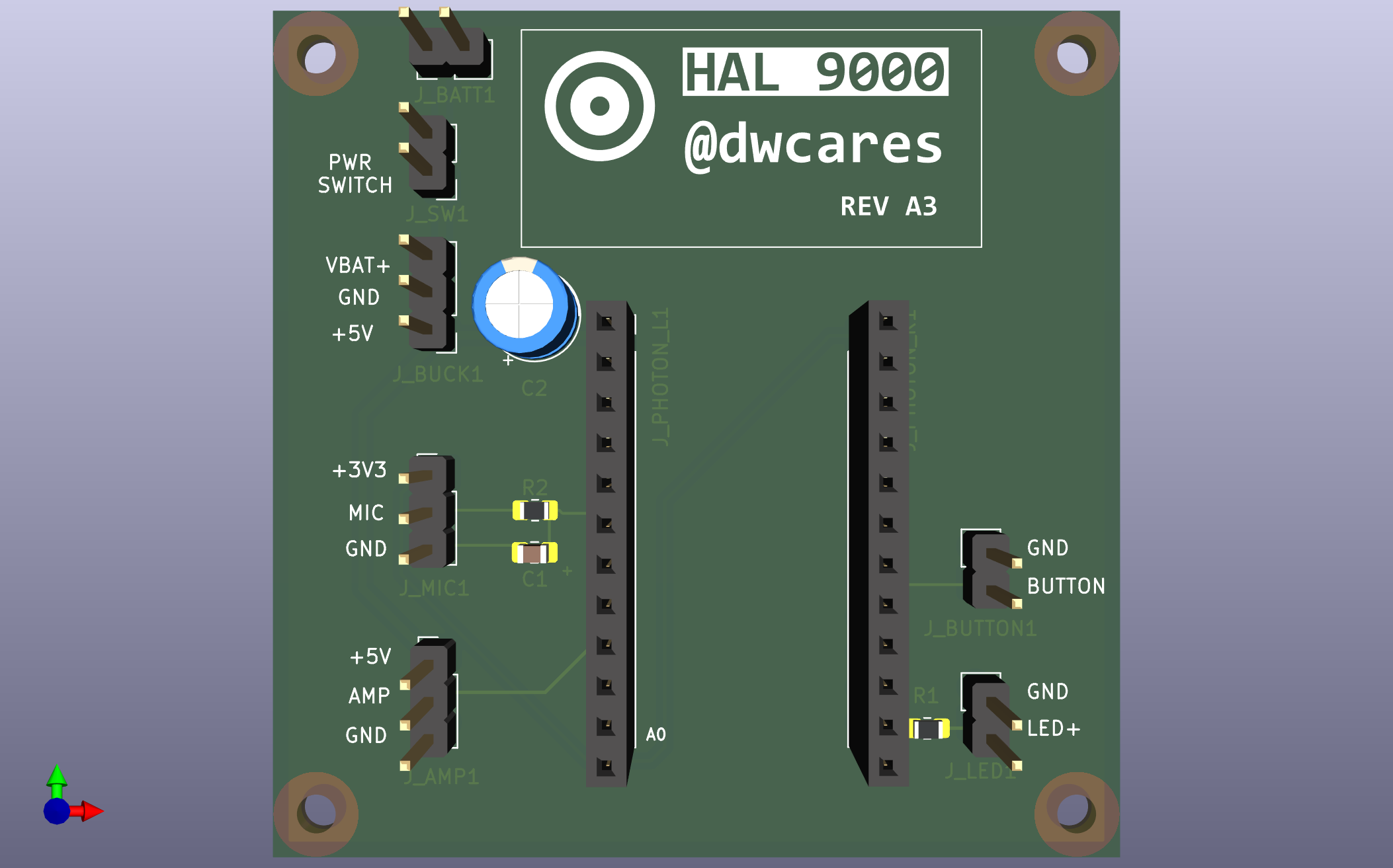
This PCB provides a clean way to connect a Particle Photon to all the peripherals needed for the voice assistant:
| File | Description |
|---|---|
hal9000.kicad_pro | KiCad project file |
hal9000.kicad_sch | Schematic |
hal9000.kicad_pcb | PCB layout |
hal9000_bom.csv | Bill of materials |
manufacturing/ | Gerber files for fabrication |
| Reference | Qty | Description | Notes |
|---|---|---|---|
| U1 | 1 | Particle Photon | Main MCU |
| J_PHOTON_L1, J_PHOTON_R1 | 2 | 12-pin Female Header 2.54mm | Photon sockets |
| J_BATT1 | 1 | 2-pin Header | Battery input (VBAT+, GND) |
| J_SW1 | 1 | 2-pin Header | Power switch |
| J_BUCK1 | 1 | 3-pin Header | Buck converter (VBAT+, GND, +5V) |
| J_MIC1 | 1 | 3-pin Header | Mic module (+3V3, MIC, GND) |
| J_AMP1 | 1 | 3-pin Header | Amp module (+5V, AMP, GND) |
| J_LED1 | 1 | 2-pin Header | LED (GND, LED+) |
| SW1 | 1 | 6mm Tactile Button | Push-to-talk |
| R1 | 1 | 220Ω 0805 | LED current limiter |
| R2 | 1 | 1kΩ 0805 | Mic input filter |
| C1 | 1 | 10nF 0805 | Mic input filter |
| C2 | 1 | 470µF Electrolytic | 5V bulk capacitance |
These modules connect via headers:
| Module | Description | Header |
|---|---|---|
| MAX9814 | Electret mic with AGC amplifier | J_MIC1 |
| PAM8302A | 2.5W Class-D mono amplifier | J_AMP1 |
| Buck/Boost Converter | 5V regulated output | J_BUCK1 |
| Signal | Photon Pin | Description |
|---|---|---|
| MIC | A6 | Microphone analog input |
| AMP | A3 (DAC) | Speaker DAC output |
| BUTTON | D4 | Push-to-talk input |
| LED | D0 | Status LED output |
The board supports battery power with an external switch:
Battery ──► J_BATT1 ──► J_SW1 (switch) ──► Buck Converter ──► J_BUCK1 (+5V out)
                                                                    │
                                                              Photon VIN
                                                                    │
Onboard 3.3V regThe manufacturing/ folder contains Gerber files ready for PCB fabrication. Upload to your preferred PCB manufacturer (JLCPCB, PCBWay, OSH Park, etc.).
MIT License - see LICENSE
| Qty | Value | Footprint | References |
|---|---|---|---|
| 4 | , , , | ||
| 4 | Conn_01x02 | Connector_PinHeader_2.54mm:PinHeader_1x02_P2.54mm_Vertical | J_BATT1, J_BUTTON1, J_LED1, J_SW1 |
| 3 | Conn_01x03 | Connector_PinHeader_2.54mm:PinHeader_1x03_P2.54mm_Vertical | J_AMP1, J_BUCK1, J_MIC1 |
| 2 | Conn_01x12 | Connector_PinSocket_2.54mm:PinSocket_1x12_P2.54mm_Vertical | J_PHOTON_L1, J_PHOTON_R1 |
| 1 | 10nF | Capacitor_SMD:C_0805_2012Metric_Pad1.18x1.45mm_HandSolder | C1 |
| 1 | 1k | Resistor_SMD:R_0805_2012Metric_Pad1.20x1.40mm_HandSolder | R2 |
| 1 | 220 | Resistor_SMD:R_0805_2012Metric_Pad1.20x1.40mm_HandSolder | R1 |
| 1 | 470uF | Capacitor_THT:CP_Radial_D6.3mm_P2.50mm | C2 |
It measures 59.9 × 59.9 mm and has 2 copper layers, 1.6 mm thick.
17 parts. The full list of its parts is on this page, with links to each part's symbol and footprint where PCBKit's library has them.
From the dwcares/hal9000 repository on GitHub, at the commit this page was made from: the board is hardware/hal9000.kicad_pcb and its schematic hardware/hal9000.kicad_sch. PCBKit opens the board in the browser, with nothing to install.
Its repository publishes it under the MIT licence: you may reuse it on that licence's terms (keep the author's notice, and for a copyleft licence share your changes alike).


hoglet67/RGBtoHDMI
Bare-metal Raspberry Pi project that provides pixel-perfect sampling of Retro Computer RGB/YUV video and conversion to HDMI


hackclub/OnBoard
💡 Join 1,000 teenagers and make your first PCB with a $100 grant!

DDeGonge/OS-ARM
This arm is not industrial and it will not be fast, but that is not my goal. But it will hopefully be a very nice looking arm fully capable of 6dof motion, cheap enough to keep it accessable but capable enough to…

