2 layers116.8 × 30 mm
Type d
google/mozc-devices
Circuit diagrams and firmware source code for Gboard DIY keyboards
14 parts3kApache-2.0

 duallain/pomodoro_clock_project1
A hobby electronics project
Pomodoro button is an open-source printed circuit board by duallain, from the duallain/pomodoro_clock_project repository on GitHub, published under the MIT licence. It is a 2-layer board of 35 × 65 mm with 14 parts on 10 nets, routed with 36 tracks and 0 vias.
Its parts include 4 resistors, 4 switches and 2 connectors.
A hobby electronics project
Pomodoros are a technique for trying to stay productive throught the day. You work for a bit, then take a break, alternate back and forth between those two, then take a longer break. I find it helpful to get focus during the work time, but not completely tire myself out. I couldn't find a physical clock I loved, and the 7 segment displays are so cool, I decided to try and build my own. And it seemed to turn out ok :)
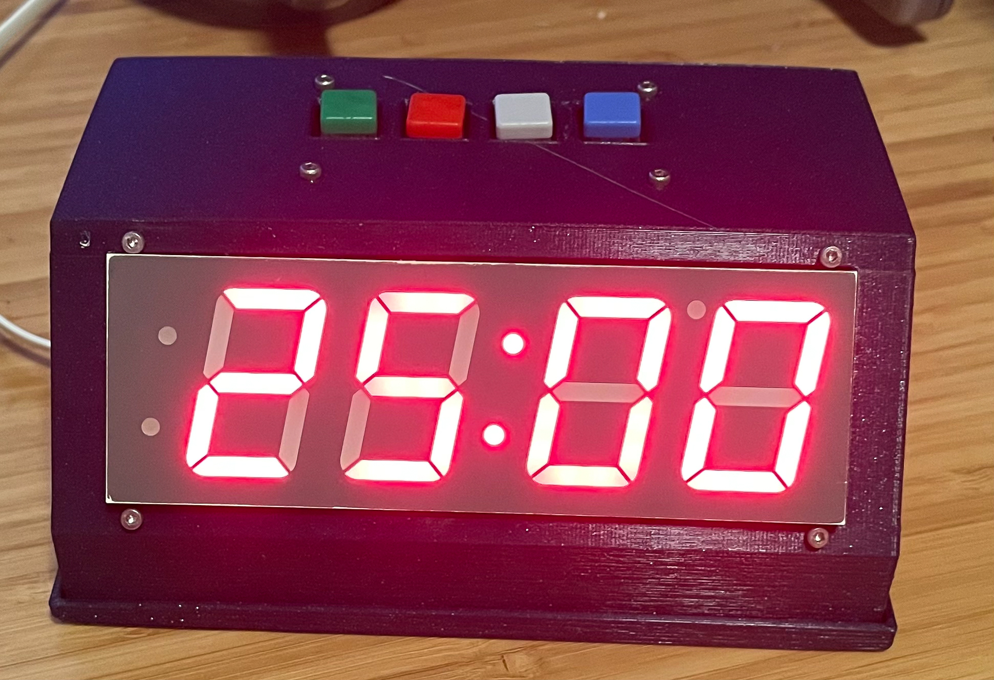
I ended up having quite a bit of trouble assembling a nice button layout on protoboards, so ended up buying 3 of the boards from osh park. The kicad files are all included in button_pcb, feel free to get some of your own manufactered.
There's a case for everything I modeled with onshape, link in the readme in case_model. Also included the stl. It's not the most efficent case, but it holds the display at a nice angle, gives space for the buttons to come throw, and they can be clicked, and hides all the wires and such. This will take a good minute to print, and I found the best orientation was the top (with the button holes) down against build plate, with supports for the display.
Solder the headers to the pi pico, I went 'backwards', putting the long parts facing towards the labeled side of the pico, it makes hitting the bootsel button harder, but easier to assemble later. I soldered both rows, but didn't add the headers to the 3 debug pins on the short ends.
This article has tons of good info, and there's lots of videos showing how to do it, but essentially solder the male headers, short end through the board. https://magpi.raspberrypi.com/articles/how-to-solder-gpio-pin-headers-to-raspberry-pi-pico (I use the breadboard method and it works wonderfully.)
I highly recommend having the pin out somewhere handy, either printed out or up on a computer. https://datasheets.raspberrypi.com/pico/Pico-R3-A4-Pinout.pdf
Follow this guide, https://learn.adafruit.com/adafruit-led-backpack/1-2-inch-7-segment-backpack-assembly
You essentially put the backpack and display together, solder all the legs, then put in a 1x5 header, solder that in and you're done.
if you have the pcb assembly is really straight forward. On the labled side you'll snap the buttons into place. There are 4 through holes per button, plus two alignment holes. Solder those in place. I found that snapping the buttons in worked great, they have plenty of strength to be flipped over and soldered. Orientation doesn't matter, they're symmetrical. You likely don't need to clip the leads, but can if you wish. Then add the resistors. You should put these all on the non-labeled side. Solder then clip. Orientation doesn't matter here either. Add the two headers, long side on the same side as the resistors (the 'bottom' of the pcb). the short bit should be on the same side as the buttons.
I used m2 screws everywhere, m2x12 to be exact, and washers and nuts. That worked for mounting both the button pcb and the display. I did this before continuing. You push the screw through the front, then put a washer/nut on it. Hold the nut with your finger, then turn the screw a bit. Do this for all 4 bolts, then go around again and tighten everything. I had to hold the nuts with a pair of needle nose pliers, but if you had a tiny little 2 mm socket that'd be ideal.
You can change pins if you wish, you'll just need to change the code.
You can pre make the cables, the 6 strand one is for button to pi. 5 strand is for display to pi. I'll label how many of the headers to use in each connection, but it's asymmetric, so be careful here. This is basically to save us from having to make a 2nd pcb to group pi pins together like we need.
Make all of these connections:
button pcb 1x2 header -> (with the 6 strand cable) 1 1x2 header to 2 1x1 headers -> 3.3v and gnd (GPIO 37/33). The square pad on the button pcb is the power, use a nice bright color button pcb 1x4 header -> (with the 6 strand cable) 1 1x4 header to 1 1x4 header -> any 4 gpio in a row (gpio10-13). You may need to change pins in the code, but any 4 gpio work. To use current code, and get buttons left to right as start/stop/reset/next, connect the square pad to gpio 10.
7 seg display 1x5 header -> (with 5 strand cable) 1 1x5 header to 1x3 and 1x2 -> 1x2 header to gp 21 and 20, the scl pin on the display goes to gp21, while sda goes to gp20. 1x3 connects to vbus/vsys/ground, gound is labeled on the display, and the +5v/v_io connect to the other two pins. Doesn't really matter which, but since they're in a row there's really only one way for it to all connect.
I used arduino ide 2.x, installed the libraries called for in the code, and then plugged in the pi pico to my computer while holding the bootsel. Click upload and it should (if everything goes well) just work. The display should be on, with the time for the first pomodoro. Click start to start counting down. Stop to stop. Reset to start from the existing timer, and next to go to the next timer. The buttons are in that order left to right while you're looking at the display.
| Qty | Value | Footprint | References |
|---|---|---|---|
| 4 | 1000 | Resistor_THT:R_Axial_DIN0207_L6.3mm_D2.5mm_P10.16mm_Horizontal | R1, R2, R3, R4 |
| 4 | SW_MEC_5E | b3f-4050:SW_B3F-4050 | SW1, SW2, SW3, SW4 |
| 1 | Conn_01x02_Male | Connector_PinHeader_2.54mm:PinHeader_1x02_P2.54mm_Vertical | J1 |
| 1 | Conn_01x04 | Connector_PinHeader_2.54mm:PinHeader_1x04_P2.54mm_Vertical | J2 |
The 10 most common of 14 parts.
google/mozc-devices
Circuit diagrams and firmware source code for Gboard DIY keyboards


hackclub/OnBoard
💡 Join 1,000 teenagers and make your first PCB with a $100 grant!


Twotoz/C5VRX
Ultra-minimal, zero-CPU 5.8 GHz analog FPV video receiver using ESP32-C5 Wi-Fi 6 PHY MODEM_DIAG, BitScrambler WBFM demodulation & resistor DAC CVBS


It measures 35 × 65 mm and has 2 copper layers, 1.6 mm thick.
14 parts. The full list of its parts is on this page, with links to each part's symbol and footprint where PCBKit's library has them.
From the duallain/pomodoro_clock_project repository on GitHub, at the commit this page was made from: the board is button_pcb/pomodoro-button.kicad_pcb. PCBKit opens the board in the browser, with nothing to install.
Its repository publishes it under the MIT licence: you may reuse it on that licence's terms (keep the author's notice, and for a copyleft licence share your changes alike).