4 layers140 × 100 mm
 dpiegdon/uart384
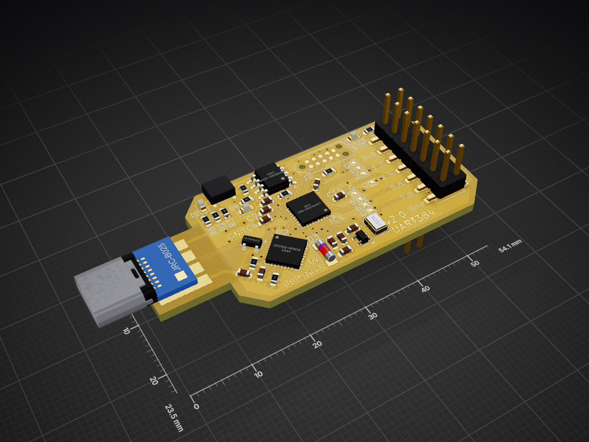
USB-based mini-devboard for the Lattice iCE40LP384 FPGA
Uart384 is an open-source printed circuit board by dpiegdon, from the dpiegdon/uart384 repository on GitHub. It is a 2-layer board of 54.1 × 23.5 mm with 52 parts on 54 nets, routed with 516 tracks and 83 vias.
It is built around the ICE40LP384-SG32, AT25DF256-SSHN-B and AMS1117-2.5, with the MIC5365-1.2YC5-TR, XC6206P182MR and LL4148 among its other parts. Its parts include 14 capacitors, 10 resistors, 6 ICs, 5 diodes and 4 connectors. It belongs with the microcontroller boards and fPGA and programmable logic boards and the FPGA and CPLD boards of this library.


This is a mini-devboard for the Lattice iCE40LP384, the BEST 🔍 FPGA ever!
Features:
NOTE: device is not programmable via USB
"Why?", you ask?
Mostly for fun and training; there are a few gateware options available in this repository:
gateware/entropy_generator.v
High quality entropy source using metastability from ringoscillators fed into the spongent hash algorithm.
This is one of the original reasons this board was created for: I wanted a USB stick that generates cryptographically sound entropy that can be used to enhance system entropy on linux.
gateware/tools/seedrng.py can be used to receive the entropy and
inject it directly into the kernel entropy pool.
gateware/relay_spi.v
This variant allows complex muxing of SPI lines from an SPI master core to all GPIO1..8 pins, as well as the internal program flash. All these pins can also be muxed as GPIO input or output and controlled/sampled. All that via a simple UART protocol.
This gives full control of inputs and outputs, as well as efficient SPI communication via SPI core, in any configuration. The SPI core is used for SPI transfer by pulling RTS down, then CS is automatically pulled down and data is seemlessly interchanged between SPI and UART.
This e.g. allows reprogramming the internal flash, or external SPI devices, including Lattice iCE40 FPGAs if GPIOs are used to trigger their CRESET. Since CDONE can also be sampled, this also allows programming any iCE40 FPGA in slave mode, fully replacing any other needed programming board to flash/program a Lattice iCE40 FPGA. Note that the FPGA is pretty much full, no further features will be added to this gateware.
See gateware/tools/spi_device.py for general SPI command abstraction,
and gateware/tools/flashtool.py and gateware/tools/spi_device.py as
an example client to work with the onboard (or any other) serial flash.
gateware/ring_noise.v
Low quality entropy generator using metastability from ringoscillators fed into a linear feedback shift register.
gateware/uart_passthrough.v
A simple example that only passes UART signals along to the GPIO header and shows changes on RX/TX lines on the LEDs (with some timeout).
gateware/variable_ringoscillator.v
Experiments with a ringoscillator with a reconfigurable delay-line. Delay can be changed at runtime via UART.
The hardware (Schematic, PCB) is licensed under CERN-OHL-W v2.
See cern_ohl_w_v2.txt.
The software is licensed under LGPL v2.0, unless specified otherwise
in a subrepository. See LGPLv2.0.txt.
| Qty | Value | Footprint | References |
|---|---|---|---|
| 8 | TestPoint | TestPoint:TestPoint_Pad_1.0x1.0mm | TP1, TP2, TP3, TP4, TP5, TP6, TP7, TP8 |
| 7 | 100n | Capacitor_SMD:C_0603_1608Metric | C1, C3, C7, C9, C10, C13, C14 |
| 5 | 10K | Resistor_SMD:R_0603_1608Metric | R1, R2, R3, R5, R10 |
| 5 | 1u | Capacitor_SMD:C_0603_1608Metric | C2, C5, C6, C11, C12 |
| 3 | 680 | Resistor_SMD:R_0603_1608Metric | R6, R7, R9 |
| 2 | 4k7 | Resistor_SMD:R_0603_1608Metric | R4, R8 |
| 2 | 4u7 | Capacitor_SMD:C_0603_1608Metric | C4, C8 |
| 1 | AMS1117-2.5 | Package_TO_SOT_SMD:SOT-223-3_TabPin2 | U4 |
| 1 | AT25DF256-SSHN | Package_SO:SOIC-8_3.9x4.9mm_P1.27mm | U1 |
| 1 | CP2102-QFN28 | Package_DFN_QFN:QFN-28-1EP_5x5mm_P0.5mm_EP3.35x3.35mm | U2 |
| 1 | Conn_02x07_Odd_Even | Connector_PinHeader_2.54mm:PinHeader_2x07_P2.54mm_Vertical_SMD | J4 |
| 1 | ICE40LP384-SG32 | Package_DFN_QFN:QFN-32-1EP_5x5mm_P0.5mm_EP3.6x3.6mm | IC1 |
| 1 | LED1_RED | LED_SMD:LED_0603_1608Metric | D4 |
| 1 | LED2_GREEN | LED_SMD:LED_0603_1608Metric | D5 |
| 1 | LED_ORANGE | LED_SMD:LED_0603_1608Metric | D2 |
| 1 | LL4148 | Diode_SMD:D_MiniMELF | D3 |
| 1 | MIC5365-1.2YC5 | Package_TO_SOT_SMD:SOT-353_SC-70-5 | U3 |
| 1 | PRTR5V0U2X | Package_TO_SOT_SMD:SOT-143 | D1 |
| 1 | SW_Push | dpiegdon:TS-1224W_Side_Button_2x4x3.3mm_3.5mm_3.8mm_SMD_Aliexpress | SW1 |
| 1 | TC2050 | Connector:Tag-Connect_TC2050-IDC-NL_2x05_P1.27mm_Vertical | J2 |
| 1 | TC2050_ext | Connector_PinHeader_2.54mm:PinHeader_2x05_P2.54mm_Vertical_SMD | J3 |
| 1 | USB_A | dpiegdon:CONN-USB-A-PCB-TRACES | J1 |
| 1 | VSEL1 | Jumper:SolderJumper-3_P1.3mm_Bridged2Bar12_RoundedPad1.0x1.5mm | JP1 |
| 1 | VSEL2 | Jumper:SolderJumper-3_P1.3mm_Open_RoundedPad1.0x1.5mm | JP2 |
| 1 | XC6206P182MR | Package_TO_SOT_SMD:SOT-23-3 | U5 |
| 1 | XO32 | Oscillator:Oscillator_SMD_EuroQuartz_XO32-4Pin_3.2x2.5mm | Y1 |
The 51 most common of 52 parts.
It measures 54.1 × 23.5 mm and has 2 copper layers, 1.6 mm thick.
52 parts, built around the ICE40LP384-SG32, AT25DF256-SSHN-B, AMS1117-2.5 and MIC5365-1.2YC5-TR. The full list of its parts is on this page, with links to each part's symbol and footprint where PCBKit's library has them.
From the dpiegdon/uart384 repository on GitHub, at the commit this page was made from: the board is pcb/uart384.kicad_pcb and its schematic pcb/uart384.kicad_sch. PCBKit opens the board in the browser, with nothing to install.
Its repository states no licence, so its author keeps all rights: ask dpiegdon before reusing the design.


tinyfpga/TinyFPGA-B-Series
Open source design files for the TinyFPGA B-Series boards.


andykarpov/karabas-pro
FPGA based retrocomputer with FDD and HDD controllers

nekonaute/pogobot
Pogobot is an open-source open-hardware robotic platform for swarm robotics