
2 layers28.3 × 39.8 mm
LevelShifter
gusmanb/logicanalyzer
24 channel, 100Msps logic analyzer hardware and software
21 parts5.1kGPL-3.0

 dorythecat/GlasgowICAdapter1
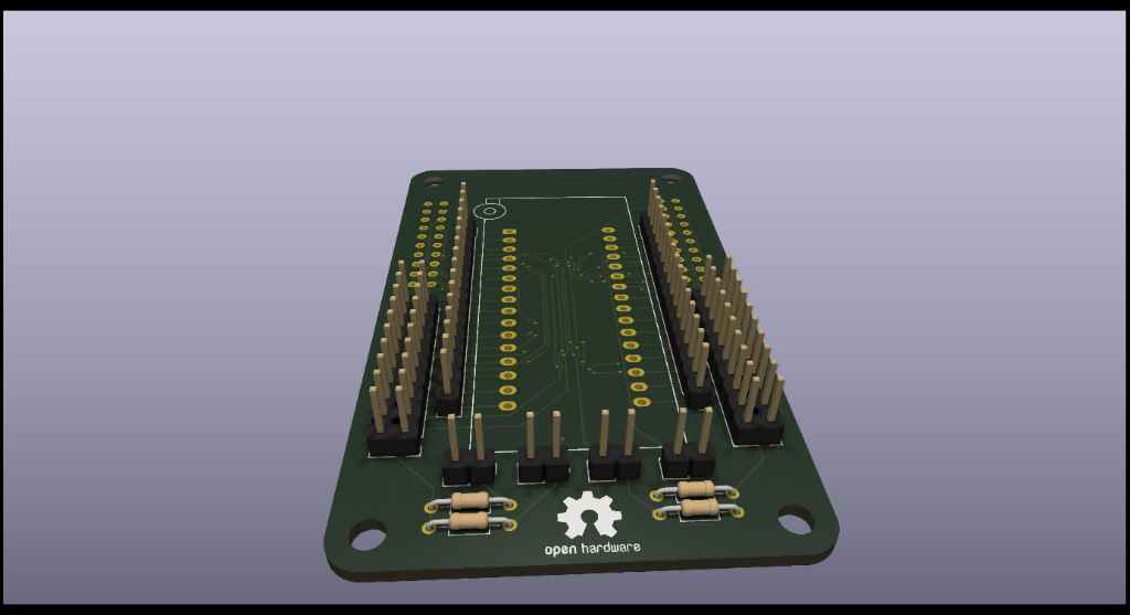
I wanted an adapter board to be able to use my ICs with my Glasgow Interface Explorer, without having to manually connect the leads one by one. It also adds some neat features.
GlasgowICAdapter is an open-source printed circuit board by dorythecat, from the dorythecat/GlasgowICAdapter repository on GitHub, published under the AGPL-3.0 licence. It is a 2-layer board of 80 × 49 mm with 21 parts on 61 nets, routed with 722 tracks and 50 vias.
It is built around the TMUX1209RSVR. Its parts include 11 connectors, 4 resistors and 4 ICs. It belongs with the interfaces and adapters boards of this library.
I wanted an adapter board to be able to use my ICs with my Glasgow Interface Explorer, without having to manually connect the leads one by one.
The design, by default, uses four TMUX1209 Dual-Channel Multiplexers, which allows the Glasgow to communicate with ICs with up to 32 pins, whilst retaining a high speed, and still have four IOs left for general use. But, the objective of this board is to be flexible. And some chips don't just need digital IO, some need analog inputs and/or outputs, and some others even need higher speeds, if with less pins. For these reasons, you can disable each one of the four multiplexers individually with the EN_Ux bridges. When these pins are bridged, the appropiate multiplexer's outputs will be disabled, and you can use the breakout besides each of the two ports, in combination with the ZIF socket breakout, and some jumper cables, in order to properly connect everything as you need it.
The multiplexers are wired 2-on-2 to each port. Four pins serve as the signal IOs (2,3,4,5), whilst two other pins (0,1), serve as the address selectors, which are wired so that both multiplexers on each channel share these address pins. The enable pins of the multiplexers are pulled up by one 10kOhm resistor each, and can be grounded by using its respective EN_Ux jumper. These multiplexe2rs support 1.8V logic, and are wired directly into the VIO of their respective port. This allows them to work with the full voltage range of the Glasgow.
| Qty | Value | Footprint | References |
|---|---|---|---|
| 4 | 10k | Resistor_THT:R_Axial_DIN0204_L3.6mm_D1.6mm_P7.62mm_Horizontal | R1, R2, R3, R4 |
| 4 | TMUX1209RSVR | TMUX1029RSVR:RSV0016A | U1, U2, U4, U5 |
| 1 | EN_U1 | Connector_PinHeader_2.54mm:PinHeader_1x02_P2.54mm_Vertical | J4 |
| 1 | EN_U2 | Connector_PinHeader_2.54mm:PinHeader_1x02_P2.54mm_Vertical | J5 |
| 1 | EN_U3 | Connector_PinHeader_2.54mm:PinHeader_1x02_P2.54mm_Vertical | J7 |
| 1 | EN_U4 | Connector_PinHeader_2.54mm:PinHeader_1x02_P2.54mm_Vertical | J8 |
| 1 | LOGO | SFH11_PBPC_D10_ST_BK:GoblinCatLogo | G*** |
| 1 | PORT A | SFH11_PBPC_D10_ST_BK:CONN_SFH11-PBPC-D10-ST-BK_SUL | J1 |
| 1 | PORT A IO | Connector_PinHeader_2.54mm:PinHeader_2x10_P2.54mm_Vertical | J10 |
| 1 | PORT B | SFH11_PBPC_D10_ST_BK:CONN_SFH11-PBPC-D10-ST-BK_SUL | J2 |
| 1 | PORT B IO | Connector_PinHeader_2.54mm:PinHeader_2x10_P2.54mm_Vertical | J11 |
| 1 | ZIF_IO_LEFT | Connector_PinHeader_2.54mm:PinHeader_1x16_P2.54mm_Vertical | J6 |
| 1 | ZIF_IO_RIGHT | Connector_PinHeader_2.54mm:PinHeader_1x16_P2.54mm_Vertical | J9 |
| 1 | ZIF_SOCKET | Socket:DIP_Socket-32_W11.9mm_W12.7mm_W15.24mm_W17.78mm_W18.5mm_3M_232-1285-00-0602J | J3 |
The 20 most common of 21 parts.
gusmanb/logicanalyzer
24 channel, 100Msps logic analyzer hardware and software

mntmn/amiga2000-gfxcard
MNT VA2000, an Open Source Amiga 2/3/4000 Graphics Card (Zorro II/III), written in Verilog


hackclub/OnBoard
💡 Join 1,000 teenagers and make your first PCB with a $100 grant!

drandyhaas/KiCadRoutingTools
A set of Python/Rust tools to aid routing in KiCad

Arrow-air/project-quiver
Project Quiver documentation, designs, and project artifacts.


It measures 80 × 49 mm and has 2 copper layers, 1.6 mm thick.
21 parts, built around the TMUX1209RSVR. The full list of its parts is on this page, with links to each part's symbol and footprint where PCBKit's library has them.
From the dorythecat/GlasgowICAdapter repository on GitHub, at the commit this page was made from: the board is GlasgowICAdapter/GlasgowICAdapter.kicad_pcb and its schematic GlasgowICAdapter/GlasgowICAdapter.kicad_sch. PCBKit opens the board in the browser, with nothing to install.
Its repository publishes it under the AGPL-3.0 licence: you may reuse it on that licence's terms (keep the author's notice, and for a copyleft licence share your changes alike).