2 layers65 × 30 mm
Rgb to hdmi
hoglet67/RGBtoHDMI
Bare-metal Raspberry Pi project that provides pixel-perfect sampling of Retro Computer RGB/YUV video and conversion to HDMI
33 parts1kGPL-3.0

 dlutz52/HD44780-tutorial-PCB
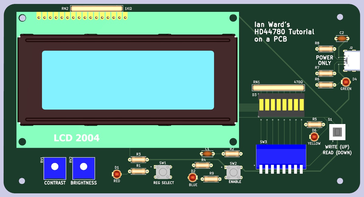
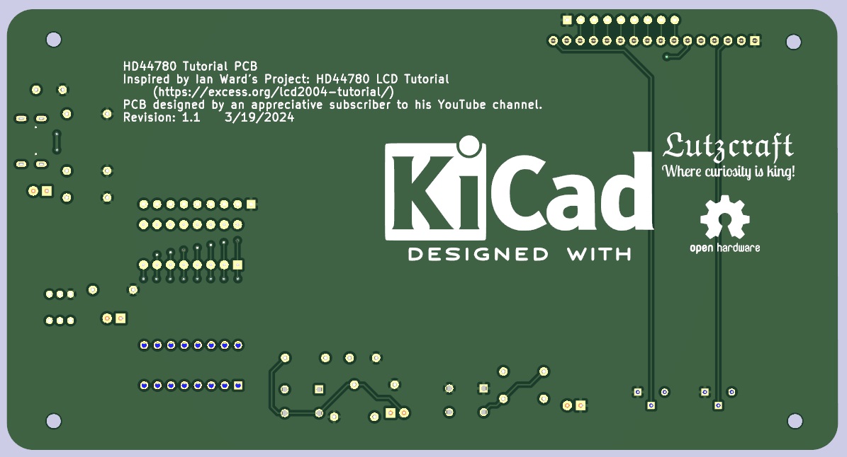
This repository contains a complete KiCad project for creating a PCB that implements the circuit design of Ian Ward in his YouTube video with the title of LCD2004 20×4 LCD Character Display with HD44780 Tutorial
Hd44780 tutorial is an open-source printed circuit board by dlutz52, from the dlutz52/HD44780-tutorial-PCB repository on GitHub, published under the GPL-3.0 licence. It is a 2-layer board of 157.2 × 83.5 mm with 33 parts on 38 nets, routed with 214 tracks and 20 vias.
It is built around the DS02C-254-1L-08BE. Its parts include 9 resistors, 5 diodes, 4 switches, 2 capacitors and 2 connectors. It belongs with the lEDs and displays boards of this library.
My inspiration for this PCB came from following Ian Ward's project on his web site:
LCD2004 20×4 LCD Character Display with HD44780 Tutorial
| Ref | Qty | Value | Vendor\Part # | Description |
|---|---|---|---|---|
| C1, C2 | 2 | .01uF | Digikey\FG28C0G1H103JNT06 | Unpolarized capacitor |
| D1 | 1 | RED | Generic | LED\3mm\Red |
| D2 | 1 | BLUE | Generic | LED\3mm\Blue |
| D3 | 1 | 8_SEG_LED BAR_GRAPH (RED) | Generic | LED Bar Graph\Red\1x8 |
| D4 | 1 | GREEN | Generic | LED\3mm\Green |
| D5 | 1 | YELLOW | Generic | LED\3mm\Yellow |
| J1 | 1 | PinSocket_1x16_P2.54mm_Vertical | Generic | Female Pin Header\1x16\2.54mm pitch |
| J2 | 1 | UJC-HP-M-G-5-MSMT-TR | Digikey\2223-UJC-HP-M-G-5-MSMT-TRDKR-ND | Type C/20 VDC/3A/Horizontal/6 Pin/Power Only |
| R1, R5, R6, R9 | 4 | 330ohm | Digikey\13-MFR-25FRF52-330RCT-ND | Resistor\330 Ohm\1%\1/4W\Axial |
| R2, R3, R4 | 3 | 1Kohm | Digikey\13-MFR-25FTE52-1KCT-ND | Resistor\1Kohm\1%\1/4W\Axial |
| R7, R8 | 2 | 5.1Kohm | Digikey\13-MFR-25FTE52-5K1CT-ND | Resistor\5K1ohm\1%\1/4W\Axial |
| RN1 | 1 | 470ohm | Digikey\4609X-101-471LF-ND | Resistor Array\ 8 Resistors\470ohm\9SIP |
| RN2 | 1 | 1Kohm | Digikey\4609X-101-102LF-ND | Resistor Array\ 8 Resistors\1Kohm\9SIP |
| RV1, RV2 | 2 | 5Kohm | Digikey\3386P-1-502LF | Trimmer Pot\5Kohms\0.5W\1/2W\Through Hole |
| S1 | 1 | TL2230 | Digikey\EG6031-ND | Switch\Pushbutton\DPDT\Through Hole |
| SW1 | 1 | REG SELECT | Digikey\450-1654-ND | Switch\Tactile\SPST-NO\0.05A\24V\Through Hole |
| SW2 | 1 | ENABLE | Digikey\450-1654-ND | Switch\Tactile\SPST-NO\0.05A\24V\Through Hole |
| SW3 | 1 | DS02C-254-1L-08BE | Digikey\2223-DS02C-254-1L-08BE-ND | Switch\Piano\8-DIP\SPST\25mA\24V\Through Hole |
The LCD and its 16-pin male header are represented only with 3D models, but you need a 2004 LCD with a soldered 16-pin male header with a pitch of 2.54mm to plug into the 16 pin female header to complete this PCB. I have found the best place to get these is on eBay.
Do NOT try to use a 2004 LCD with an I2C adapter on it.
Most symbols/footprints/models are contained under the 'libraries' directory. Capacitors, resistors and LEDs use KiCad symbols/footprints/models.
KiCad 7.0.10 was used to create this PCB. KiCad 8.0.1 is out now and this project opens in that version. The newer KiCad will warn that this project was created in previous version and will be saved in a the newer format. When closing the schematic or a PCB just discard any changes. If you do not you will not be able to use KiCad 7 any more without difficulties.
Some models in KiCad's 3D view will display an appropriate socket under them but these can be omitted on the PCB - they are used to make it easier to replace any components should they need it in the future.
| Qty | Value | Footprint | References |
|---|---|---|---|
| 4 | 330Ω | Resistor_THT:R_Axial_DIN0207_L6.3mm_D2.5mm_P7.62mm_Horizontal | R1, R5, R6, R9 |
| 4 | MountingHole | MountingHole:MountingHole_2.7mm_M2.5 | H1, H2, H3, H4 |
| 3 | 1KΩ | Resistor_THT:R_Axial_DIN0207_L6.3mm_D2.5mm_P7.62mm_Horizontal | R2, R3, R4 |
| 2 | .01uF | Capacitor_THT:C_Disc_D4.7mm_W2.5mm_P5.00mm | C1, C2 |
| 2 | 5.1K | Resistor_THT:R_Axial_DIN0207_L6.3mm_D2.5mm_P7.62mm_Horizontal | R7, R8 |
| 2 | 5KΩ | HD44780-tutorial-PCB:BOURNE-3386P | RV1, RV2 |
| 1 | 8_SEG_LED BAR_GRAPH | HD44780-tutorial-PCB:LED_Bar_Graph_8_SEG_SOCKET | D3 |
| 1 | 1KΩ | HD44780-tutorial-PCB:R_Array_SIP9 | RN2 |
| 1 | 470Ω | HD44780-tutorial-PCB:R_Array_SIP9 | RN1 |
| 1 | BLUE | LED_THT:LED_D3.0mm | D2 |
| 1 | DS02C-254-1L-08BE | HD44780-tutorial-PCB:SW_DS02C-254-1L-08BE | SW3 |
| 1 | ENABLE | HD44780-tutorial-PCB:SW_1825967-1 | SW2 |
| 1 | GREEN | LED_THT:LED_D3.0mm | D4 |
| 1 | LCD_2004_PinSocket_1x16_P2.54mm_Vertical | HD44780-tutorial-PCB:LCD_2004_PinSocket_1x16_P2.54mm_Vertical | J1 |
| 1 | LOGO | HD44780-tutorial-PCB:Lutzcraft_logo_1125DPI | G*** |
| 1 | RED | LED_THT:LED_D3.0mm | D1 |
| 1 | REG SELECT | HD44780-tutorial-PCB:SW_1825967-1 | SW1 |
| 1 | TL2230 | HD44780-tutorial-PCB:TL2230EEF140 | S1 |
| 1 | USB RECEPTACLE | HD44780-tutorial-PCB:CUI_UJC-HP-M-G-5-MSMT-TR | J2 |
| 1 | YELLOW | LED_THT:LED_D3.0mm | D6 |
The 31 most common of 33 parts.
It measures 157.2 × 83.5 mm and has 2 copper layers, 1.6 mm thick.
33 parts, built around the DS02C-254-1L-08BE. The full list of its parts is on this page, with links to each part's symbol and footprint where PCBKit's library has them.
From the dlutz52/HD44780-tutorial-PCB repository on GitHub, at the commit this page was made from: the board is hd44780_tutorial.kicad_pcb and its schematic hd44780_tutorial.kicad_sch. PCBKit opens the board in the browser, with nothing to install.
Its repository publishes it under the GPL-3.0 licence: you may reuse it on that licence's terms (keep the author's notice, and for a copyleft licence share your changes alike).
hoglet67/RGBtoHDMI
Bare-metal Raspberry Pi project that provides pixel-perfect sampling of Retro Computer RGB/YUV video and conversion to HDMI

mntmn/amiga2000-gfxcard
MNT VA2000, an Open Source Amiga 2/3/4000 Graphics Card (Zorro II/III), written in Verilog

hackclub/OnBoard
💡 Join 1,000 teenagers and make your first PCB with a $100 grant!

Arrow-air/project-quiver
Project Quiver documentation, designs, and project artifacts.

ozel/DIY_particle_detector
A mobile low-cost spectrometer for measuring radioactivity and the energy of ionising radiation like alpha particles and electrons

BlueAndi/Pixelix
Full RGB LED matrix, based on an ESP32 and WS2812B LEDs or emulated LEDs on TFT.

jrsteensen/OpenHornet
OpenHornet 1:1 F/A-18C Simulator Repository
