
2 layers103 × 30.5 mm

 dkgrizzly/A2Relay1
Apple II Gameport Relay Interface
A2Relay is an open-source printed circuit board by dkgrizzly, from the dkgrizzly/A2Relay repository on GitHub, published under the Unlicense licence. It is a 2-layer board of 33 × 30.5 mm with 9 parts on 25 nets, routed with 94 tracks and 0 vias.
It is built around the SN74ALS259D and SN74ALS259DRE4. Its parts include 4 connectors, 2 capacitors and 2 ICs. It belongs with the home automation and IoT and retro computing and games boards of this library.
[!WARNING] This design is currently untested as of 5/26/2026. There may be errors in the design or example code.
Update 6/12/2026: Because the 74_259 resets to all outputs low and the relay module is active low, all the relays default to being on at startup. Adding a 74_240 inline between the 74_259 and relay board will correct for this in a future revision.
Schematics and Gerbers for an "OOPS! Inverter" board will be uploaded soon.
[!CAUTION] It is advisable to remove the VCC jumper on the relay board and power the relays with the GND and JD-VCC pin. The game port is designed to provide a maximum of 100ma, and with all relays turned on more than 500ma load will be present.
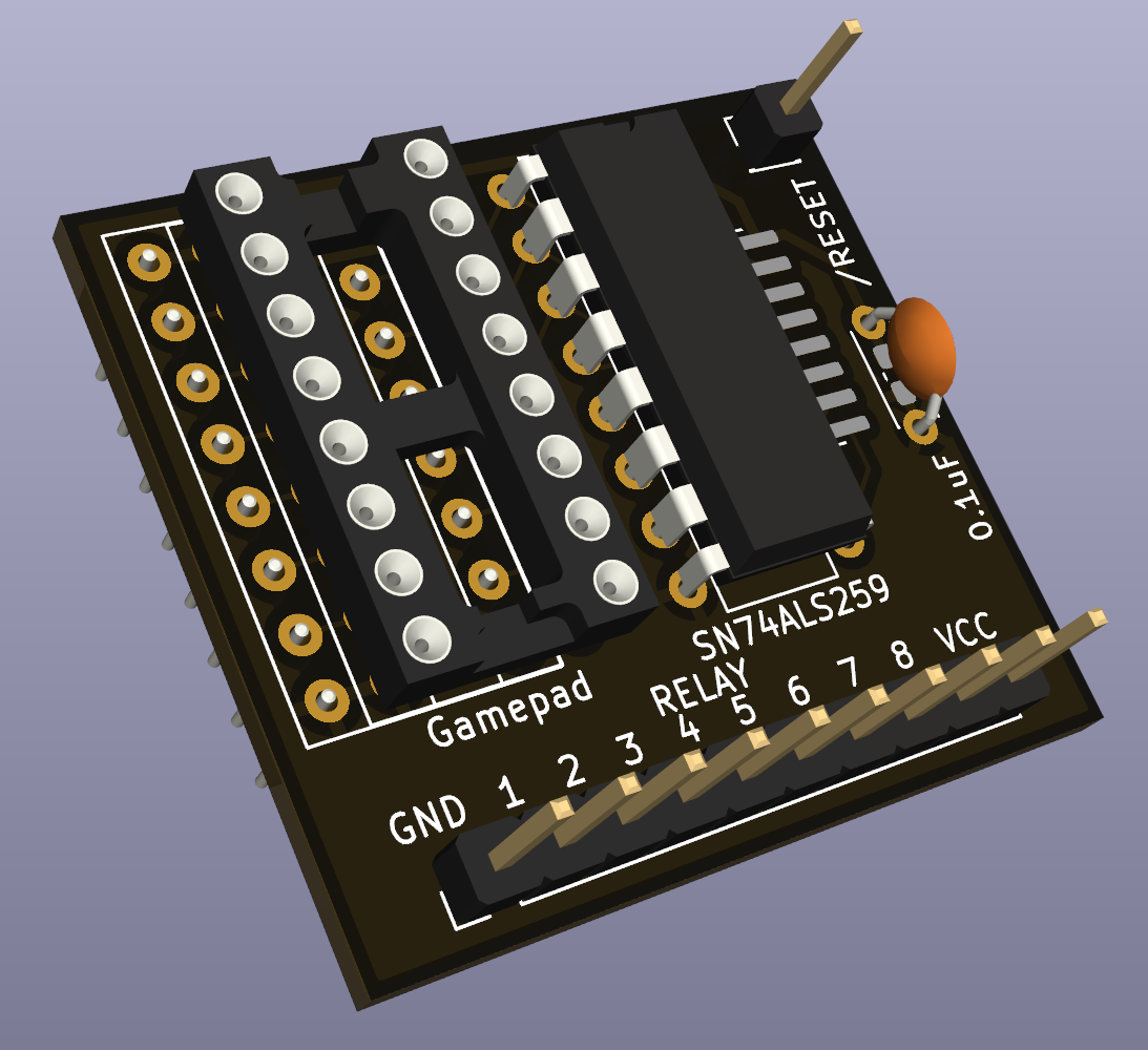
This is a design for a small PCB to control inexpensive 8-relay modules (Amazon affiliate link) using the Apple II's gameport annunciators and strobe output. Use AN3 to set on/off state, AN0-AN2 to select which relay to control, and $C040 strobe to store the value. All pins are passed through to a socket where you can attach a gamepad, paddles, or other input device.
10 REM To turn on the first relay:
20 PEEK -16295 : REM Clear AN0 $C059
30 PEEK -16293 : REM Clear AN1 $C05B
40 PEEK -16291 : REM Clear AN2 $C05D
50 PEEK -16290 : REM  Set  AN3 $C05E
60 PEEK -16320 : REM Strobe $C0400300 lda $C059 ; Clear AN0
0303 lda $C05B ; Clear AN1
0306 lda $C05D ; Clear AN2
0309 lda $C05E ; Set AN3
030c lda $C040 ; Strobe
030f rts| Qty | Value | Footprint | References |
|---|---|---|---|
| 1 | /RESET | Connector_PinHeader_2.54mm:PinHeader_1x01_P2.54mm_Vertical | J3 |
| 1 | 0.1uF | Capacitor_SMD:C_0603_1608Metric_Pad1.08x0.95mm_HandSolder | C2 |
| 1 | 0.1uF | Capacitor_THT:C_Disc_D4.3mm_W1.9mm_P5.00mm | C1 |
| 1 | Gamepad | Package_DIP:DIP-16_W7.62mm | J2 |
| 1 | Gameport | Package_DIP:DIP-16_W7.62mm_Socket | J1 |
| 1 | LOGO | cityxen:deadline97 | G*** |
| 1 | RELAY | Connector_PinHeader_2.54mm:PinHeader_1x10_P2.54mm_Vertical | J4 |
| 1 | SN74ALS259 | Package_DIP:DIP-16_W7.62mm | U1 |
| 1 | SN74ALS259DR | Package_SO:SOIC-16_3.9x9.9mm_P1.27mm | U2 |


FrameworkComputer/ExpansionCards
Reference designs and documentation to create Expansion Cards for the Framework Laptop

VoronDesign/Voron-Hardware
Cool Hardware designed by the Voron Design group

hackclub/OnBoard
💡 Join 1,000 teenagers and make your first PCB with a $100 grant!


adamws/kicad-kbplacer
KiCad plugin for automatic keyboard's key placement and routing
It measures 33 × 30.5 mm and has 2 copper layers, 1.6 mm thick.
9 parts, built around the SN74ALS259D and SN74ALS259DRE4. The full list of its parts is on this page, with links to each part's symbol and footprint where PCBKit's library has them.
From the dkgrizzly/A2Relay repository on GitHub, at the commit this page was made from: the board is A2Relay.kicad_pcb and its schematic A2Relay.kicad_sch. PCBKit opens the board in the browser, with nothing to install.
Its repository publishes it under the Unlicense licence: you may reuse it on that licence's terms (keep the author's notice, and for a copyleft licence share your changes alike).