2 layers184 × 80.5 mm
Prometheus PCB
TheContrappostoShop/Apollo
Control Board for the Prometheus mSLA Printer.
129 parts13CERN-OHL-S-2.0

 dj505/Untitled
A badge thing
BadgeThing is an open-source printed circuit board by dj505, from the dj505/Untitled repository on GitHub. It is a 2-layer board of 78.7 × 40.2 mm with 74 parts on 89 nets, routed with 500 tracks and 40 vias.
It is built around the RP2040, ESP-12F and W25Q32JVSSIQ, with the USBLC6-2SC6 and WS2812B among its other parts. Its parts include 24 capacitors, 15 connectors, 12 resistors, 7 switches and 6 ICs. It belongs with the ESP8266 and RP2040 boards of this library.


A small homebrew dev board, previously known as BadgeThing
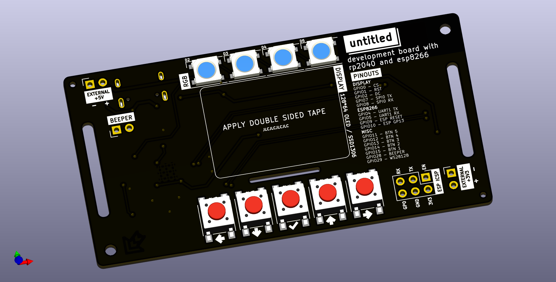
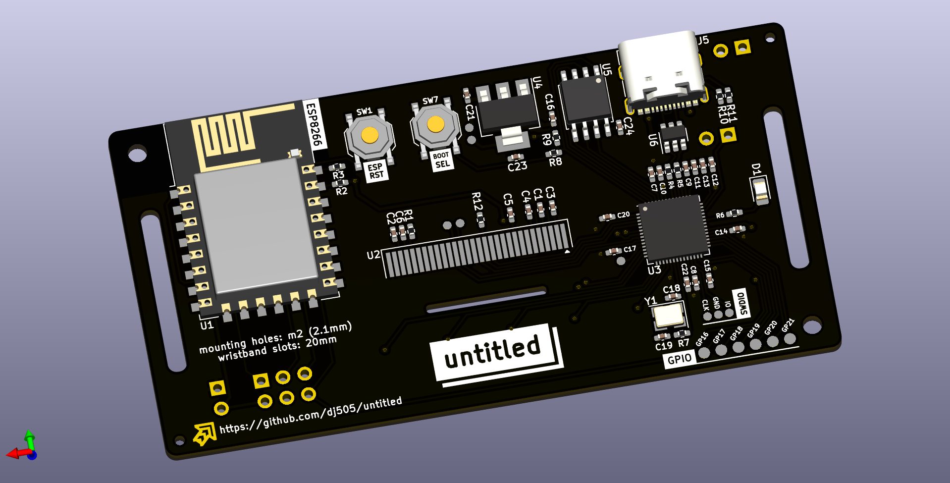
Untitled is a software-focused development board, and an excuse for me to learn a bit more about some specific hardware I'd like to incorporate into future projects. The main focus is the integrated SSD1306 OLED display, which I've used in earlier projects as a separate module. This time around, I wanted to adapt the circuit into the project itself to make the whole thing more cohesive.
I figured since it was going to have a screen, I needed to be able to use the screen for something, so I included hardware I was already familiar with to interface with. There's the RP2040 I've used in other previous projects, and I've played with the ESP8266 before in the context of Arduino-like programming, so I thought I would try integrating that into this design so I could play with the AT firmware a little. I've used WS2812B LEDs a ton and thought they'd make a good set of indicators. And, since I wanted this to be versatile, it features some screw holes as well as slits along either side to mount using a wrist strap or some type of band to attach to other things without screws. It could even be wearable!
Oh, and it's called "Untitled" because I couldn't think of a witty name for this one. I originally wanted to call it the "no name development board with rp2040 and esp8266" with a logo and black/yellow colour scheme that parody the Canadian "no name" brand, but JLC doesn't offer black silkscreen on yellow solder mask, so I had to change it up.
I couldn't find an easy-to-place foorptint for the 30-pin SSD1306 display, so this project includes a custom KICAD footprint for the typical 12mm length/7mm pin pitch ribbon cable variant you can find for cheap on AliExpress. There are 4 variants, two meant for mounting the screen on the front of the board, and two for mounting it on the back. Both placements have variants including and excluding a cutout in the Edge.Cuts layer for the ribbon cable to pass through. You are free to use these footprints in any project you want! I just ask that credit is provided.
There is also a custom symbol in the schematic for the display, based off of Adafruit's schematic. I can't guarantee all the pins are labelled correctly. I have tested it, and it does work, but you should research and double check the correct pinouts for your own project.
If you end up using either of these, and found them useful, please consider sending a small tip my way!

The majority of the parts are clearly labelled in the schematic and/or come with LCSC part numbers available through JLC. Not all of them are basic parts, unfortunately, but I used as many as I possibly could. You're also free to order part like the ESP-12 module separately and solder it yourself to save on assembly costs. However, it's important to keep in mind the following:
As this project is meant to be mainly for personal use, I won't go into extensive detail here on how to order this board for assembly. However, a pre-made gerber zip is included in the "production" directory, and the BOM/CPL files can be generated through KiCAD. I recommend using the JLCPCB export plugin to do the heavy lifting for you - the LCSC part numbers I used for most components should be included in the schematic. Feel free to poke me with questions over Discord! You can reach me @dj505.
| Qty | Value | Footprint | References |
|---|---|---|---|
| 11 | 100nF | Capacitor_SMD:C_0402_1005Metric_Pad0.74x0.62mm_HandSolder | C7, C8, C10, C12, C13, C14, C15, C17, C20, C22, C24 |
| 8 | Conn_01x01 | Connector_PinHeader_2.00mm:PinHeader_1x01_P2.00mm_Vertical | J8, J9, J10, J11, J12, J13, J14, J15 |
| 5 | 2.2uF | Capacitor_SMD:C_0402_1005Metric_Pad0.74x0.62mm_HandSolder | C1, C3, C4, C5, C6 |
| 4 | WS2812B | LED_SMD:LED_WS2812B_PLCC4_5.0x5.0mm_P3.2mm | D2, D3, D4, D5 |
| 3 | 10uF | Capacitor_SMD:C_0402_1005Metric_Pad0.74x0.62mm_HandSolder | C2, C21, C23 |
| 2 | 10K | Resistor_SMD:R_0402_1005Metric_Pad0.72x0.64mm_HandSolder | R2, R3 |
| 2 | 1k | Resistor_SMD:R_0402_1005Metric_Pad0.72x0.64mm_HandSolder | R7, R8 |
| 2 | 1uF | Capacitor_SMD:C_0402_1005Metric_Pad0.74x0.62mm_HandSolder | C9, C11 |
| 2 | 27 Ohm | Resistor_SMD:R_0402_1005Metric_Pad0.72x0.64mm_HandSolder | R4, R5 |
| 2 | 27pF | Capacitor_SMD:C_0402_1005Metric_Pad0.74x0.62mm_HandSolder | C18, C19 |
| 2 | 5.1k | Resistor_SMD:R_0402_1005Metric_Pad0.72x0.64mm_HandSolder | R10, R11 |
| 1 | 12.000MHz | Crystal:Crystal_SMD_3225-4Pin_3.2x2.5mm | Y1 |
| 1 | 220 Ohm | Resistor_SMD:R_0402_1005Metric_Pad0.72x0.64mm_HandSolder | R6 |
| 1 | 270k | Resistor_SMD:R_0402_1005Metric_Pad0.72x0.64mm_HandSolder | R1 |
| 1 | 4.7k | Resistor_SMD:R_0402_1005Metric_Pad0.72x0.64mm_HandSolder | R12 |
| 1 | BOOTSEL | Button_Switch_SMD:SW_Push_1P1T_XKB_TS-1187A | SW7 |
| 1 | Conn_01x06 | Connector_PinHeader_2.00mm:PinHeader_1x06_P2.00mm_Vertical | J7 |
| 1 | Connector_Generic_Conn_01x02 | Connector_PinHeader_2.54mm:PinHeader_1x02_P2.54mm_Vertical | J6 |
| 1 | DNF | Resistor_SMD:R_0402_1005Metric_Pad0.72x0.64mm_HandSolder | R9 |
| 1 | DNF | LED_SMD:LED_0805_2012Metric_Pad1.15x1.40mm_HandSolder | D1 |
| 1 | Down | Button_Switch_SMD:SW_Push_1P1T_NO_6x6mm_H9.5mm | SW3 |
| 1 | ESP RESET | Button_Switch_SMD:SW_Push_1P1T_XKB_TS-1187A | SW1 |
| 1 | ESP-12F | RF_Module:ESP-12E | U1 |
| 1 | Ext 5V | Connector_PinHeader_2.54mm:PinHeader_1x02_P2.54mm_Vertical | J2 |
| 1 | External 3V3 | Connector_PinHeader_2.54mm:PinHeader_1x02_P2.54mm_Vertical | J3 |
| 1 | Left | Button_Switch_SMD:SW_Push_1P1T_NO_6x6mm_H9.5mm | SW2 |
| 1 | NCP1117-3.3_SOT223 | Package_TO_SOT_SMD:SOT-223-3_TabPin2 | U4 |
| 1 | RP2040 | RP2040_minimal:RP2040-QFN-56 | U3 |
| 1 | Right | Button_Switch_SMD:SW_Push_1P1T_NO_6x6mm_H9.5mm | SW6 |
| 1 | SWD Header | Connector_PinHeader_1.27mm:PinHeader_1x03_P1.27mm_Vertical | J4 |
| 1 | Select | Button_Switch_SMD:SW_Push_1P1T_NO_6x6mm_H9.5mm | SW4 |
| 1 | USBLC6-2SC6 | Package_TO_SOT_SMD:SOT-23-6 | U6 |
| 1 | USB_C_Receptacle_USB2.0 | Connector_USB:USB_C_Receptacle_G-Switch_GT-USB-7010ASV | J5 |
| 1 | Up | Button_Switch_SMD:SW_Push_1P1T_NO_6x6mm_H9.5mm | SW5 |
| 1 | W25Q32JVSS | Package_SO:SOIC-8_5.23x5.23mm_P1.27mm | U5 |
| 1 | beeg | Capacitor_SMD:C_0402_1005Metric_Pad0.74x0.62mm_HandSolder | C16 |
| 1 | ~ | SSD1306 Pins:SSD1306 0.5mm Pitch | U2 |
| 1 | ~ | Connector_PinHeader_2.54mm:PinHeader_2x03_P2.54mm_Vertical | J1 |
The 70 most common of 74 parts.
It measures 78.7 × 40.2 mm and has 2 copper layers, 1.6 mm thick.
74 parts, built around the RP2040, ESP-12F, W25Q32JVSSIQ and USBLC6-2SC6. The full list of its parts is on this page, with links to each part's symbol and footprint where PCBKit's library has them.
From the dj505/Untitled repository on GitHub, at the commit this page was made from: the board is BadgeThing.kicad_pcb and its schematic BadgeThing.kicad_sch. PCBKit opens the board in the browser, with nothing to install.
Its repository states no licence, so its author keeps all rights: ask dj505 before reusing the design.
TheContrappostoShop/Apollo
Control Board for the Prometheus mSLA Printer.

nimitvijayvargee/trhw
This is an RP2040 ruler that implements wifi, bluetooth, BLE along with a 4MB Flash storage, LEDs, Input buttons and some cool units and lengths!


TheContrappostoShop/Hercules_Sensor
Hercules is the open-source force sensor made for the Prometheus mSLA, based on the idea of Nico Martin.

vinnesttree/TixClock
The Tix Clock was originally sold in 2006 by ThinkGeek. Unfortunately, these are no longer sold. This project hopes to try to recreate this iconic clock in a miniature format.